Randy's RCR40 MKI

Randy Folsom

Supporter
Can you tell us what that glass is doing? I can't quite tell in the photos. I can see the larger gap toward the bottom of the A-pillar but is it gapping away from the pillar down there and the A-pillar should be forward more? Not sure I understand where you're taking off material. Thanks!
The glass fits the top and bottom profiles perfectly allowing for a nice 1/8” to 3/16” gap along both the top and bottom.

However, the glass is too wide to slide up in the frame, so currently there is no gap at the bottom and 3/8” gap at the top. A lot of that extra width can be fixed by sanding the side edges straight to match the A-pillars. Today, I am going to try a random, orbital with 3M’s Cubitron sandpaper.
 

Randy Folsom

Supporter
Randy, thank you for sharing, I measure the work to accomplish, and I am glad that it was already do,ne on my car.
I bought this car more for the building than the driving. To me it’s like a good book. I used to only buy books with at least 500 pages because I wanted them to last. Same for this car. I am in no hurry to finish as long as I am enjoying the process.
 

Paul T.

Supporter
The glass fits the top and bottom profiles perfectly allowing for a nice 1/8” to 3/16” gap along both the top and bottom.

However, the glass is too wide to slide up in the frame, so currently there is no gap at the bottom and 3/8” gap at the top. A lot of that extra width can be fixed by sanding the side edges straight to match the A-pillars. Today, I am going to try a random, orbital with 3M’s Cubitron sandpaper.
Figured mine couldn't be the only one that fit like that. Will be doing the same.
 

Ian Anderson

Lifetime Supporter
I must say you are brave trimming the glass

I would have adjusted the fiberglass surround instead.

2 reasons 1 I do not fancy breathing glass dust

2 when /if you break or crack that windscreen down the line you will need to carry out the same surgery to the next screen. Instead of just placing it in the adjusted aperture
 

Randy Folsom

Supporter
Windshield

More sanding today. I found that the random orbital sander doesn’t work as well as the belt sander, but the belt sander generates heat much faster so it’s important to switch sides frequently. In any event I can’t sand for very long because this beast is great for floors but gets heavy fast.
image.jpg
 

Randy Folsom

Supporter
I must say you are brave trimming the glass

I would have adjusted the fiberglass surround instead.

2 reasons 1 I do not fancy breathing glass dust

2 when /if you break or crack that windscreen down the line you will need to carry out the same surgery to the next screen. Instead of just placing it in the adjusted aperture
Ian,

Yes, I am pretty sure glass dust is not healthy. I am wearing a mask and have a fan blowing from behind me to carry the dust away from me.

Unfortunately, adjusting the aperture is not really an option because of the amount of adjustment required. Basically, the A-pillars are straight and the side edges of the windshield bow outward by 3/16”. If I cut the pillar ridge to fit the glass it would look ridiculously thin. Bending the pillar is not an option because then the doors would not fit.

So the solution is either pay someone to grind it for me (which would require knowing exactly how much the trim and where) or continue to slowly sand and test until it fits.

If it breaks, at least I can use the pieces as a template for a glass shop to sand down a replacement.

Cheers, Randy
 

Randy Folsom

Supporter
Windshield Day 3

I found that an office chair works well to support the windshield while sanding. Note the large rubber mat under the chair.

I beveled the edges constantly using 150-grit with a 5” orbital sander. The orbital sander does not heat up the glass because it is drawing air through the disk. Unfortunately, it also doesn’t remove much material. The beveling reduces edge chipping when using the belt sander. I went through so many disks and belts. Tempered glass is hard. I am just about finished. Just a 1/32” to go in a few locations. Saving that for tomorrow.

IMG_3852.jpeg
 
Windshield Day 3

I found that an office chair works well to support the windshield while sanding. Note the large rubber mat under the chair.

I beveled the edges constantly using 150-grit with a 5” orbital sander. The orbital sander does not heat up the glass because it is drawing air through the disk. Unfortunately, it also doesn’t remove much material. The beveling reduces edge chipping when using the belt sander. I went through so many disks and belts. Tempered glass is hard. I am just about finished. Just a 1/32” to go in a few locations. Saving that for tomorrow.

View attachment 139970
Can a glass company trim these versus all the time in sanding?
 

Randy Folsom

Supporter
Can a glass company trim these versus all the time in sanding?
Probably, but I thought it would be really hard to determine how much and where to trim since the glass edge was curved outward from top to bottom and the A-pillar is relatively straight. Can’t just say take off 1/8” on each side. Also, the curve was more pronounced on the bottom on the DS and nearer the top on the PS so there is no reference for the angle. I suppose one could bring the spider to the glass shop, but because the spider has to be propped up when fitting the glass, that might have resulted in more problems.

Turns out I thought of a way to provide that guidance after I was just about done.

I could have used a Sharpie to draw a ref line along each edge, then measured from the ridge on the A-pillar to the ref line every three inches and written those measurements right on the glass.

Taking the measurements would have been a challenge since the glass is laying on top of the ridge, but I think it would have been good enough.

If I ever have to do this again, I will use the ref line method.
 
Do you have the “new style“ steering rack on your RCR? If so, the provided fittings don’t work with the new rack? The DD on the rack is 20.1mm vs the 3/4 (19.05mm) fittings. Have you tried that yet?
 

Randy Folsom

Supporter
Do you have the “new style“ steering rack on your RCR? If so, the provided fittings don’t work with the new rack? The DD on the rack is 20.1mm vs the 3/4 (19.05mm) fittings. Have you tried that yet?
Jeff,
Thx for the heads up about the shaft size.
I have not received my rack yet. I will probably upgrade my steering column to a single straight bar with a collapsible section. I am looking at the SCA700 column and SBC80-1 mount from Woodward Steering as an option. I will definitely check the sizes before ordering.


Cheers, Randy
Was wondering if your setup was the same. Guessing it is.
 

Randy Folsom

Supporter
Windshield Day 5

Took a few days off to visit my daughter and her growing family in Houston. I’ll spare you the grandchildren stories :)

I finally finished sanding down the sides. The gaps at the top and bottom are more or less uniform at about 1/4”. The sides are about 3/32” and align nicely with the A-pillar ribs. I will repaint the frit. I had no idea what this black edge paint had a special name. I also learned that it provides both a bonding surface for the adhesive and protects the adhesive from UV. Hope I can replicate the crisp edge.

I found this one on Amazon

Everything came out very nice. I spent a lot of time making sure the edges were as smooth as a baby’s you know what. I figure any little defect could lead to a crack down the road.

After all this, I don’t recommend doing it yourself. The reason I didn’t take it too a glazier was because I didn’t know how to tell them how much to take off. I figured it out when I was almost done. See my response to Jeff B. above.

After all that fitting it was nice to see that the spider nearly touches the top center of the glass without any support. There is a gap between the PS A-pillar midway down the pillar. I can close the gap with a light squeeze so I think the adhesive will hold without issue.

IMG_3868.jpeg


IMG_3866.jpeg
 
Last edited:

Randy Folsom

Supporter
Electric Parking Brake

I really didn’t want a hand brake taking up space in an already crowded interior and I had read in multiple build logs that they don’t work very well.

Therefore, I decided to go with an electric parking brake system. I looked at the available offering such as the E-Stopp, but they are too long to fit so I put together a bespoke electric parking brake system. The whole system cost about $130 on Amazon, but $32 of that was shipping.

I used two 25mm linear actuators mounted inside the engine surround, one for each side, anchored to the lower bulkhead. The cables are from the RCR kit, but shortened to about three feet. The brake is activated/deactivated with a Forward and Reverse Relay Module and a Latching Push Button Switch.

My first step was to install the actuator anchors. I chose an anchor location that avoids interference with the lower suspension link and provides a fairly direct cable path.

I used a wooden block as a drill guide for the anchor mounting. I drilled the block using one of the provided anchor brackets as a template. I then clamped the block to the bulkhead positioned such that the bottom inboard hole is 6-1/4” from top edge and 2-1/8” from tub wall. My goal was to allow for access while avoiding blocking the opening and associated cover fasteners. I also wanted enough space to drill the holes. I used an air drill because it has a small head. I made sure there was enough room inside the tub surround to insert the bolts and reach up to insert the cotter pin through the anchor pin. Note that the wall inside the engine surround is doubled so there is 1/4” less space between the bracket and wall than as measured in the passenger area. I drilled out the anchor bracket holes to 5/16” so I wouldn’t have to fight too hard to insert the bolts in that tight space. I also used washers under the bolt heads to keep the ends of the bolts from protruding past the bulkhead.

The next step was to modify the cabling provided by RCR. I did the following:
  • Cut off the ferrel at the hand brake end of the internal twisted cable
  • Disassembled the cable
  • Shortened the return spring to between 7-1/2” and 8”
  • Discarded the rubber washers
  • Cut the cable housing to 18”
  • Cut the twisted cable 5” to 6” beyond the cable housing (about three feet total length)
  • Cut the rubber sleeve to the same length as the cable housing
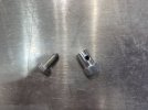
The RCR provided cables are thicker than common parking brake cables. I could not find a removable ferrel the correct size. So I used the part listed below, but discarded the ball bearing, drilled out the hole to fit the cable snugly and ground a 45^ point on the bolt.

I then fabricated a U-bracket from thin flat-bar, 3/4” wide. I made the bracket long enough to allow the twisted cable to bend away from the actuator. I started with a 6” long piece, bent it around a 7/16 bolt, then drilled holes for the pin at the ends and a hole for the cable in the middle.

I mounted the cable bracket as described in the online manual. For the cable hole, I found it easier to drill straight in with a step bit rather than at an angle. I then used a round file to bevel the edges to match the cable path.

The last thing I did before final assembly was to bend the angle bracket that is on the caliper. This step provides a better cable mounting angle and ensures tire clearance.

Parts

Installed (the picture is upside down)
IMG_3882.jpeg


IMG_3880.jpeg


IMG_3881.jpeg


IMG_3879.jpeg


IMG_3878.jpeg


IMG_3883.jpeg
 

Attachments

  • IMG_3878.jpeg
    IMG_3878.jpeg
    385.4 KB · Views: 50
Last edited:

Randy Folsom

Supporter
Electric Parking Brake

Some notes about actuators. I am by no means an expert, but I did learn a few things about actuators. Most importantly is they must be able to travel until they hit a limit switch. Otherwise the motor will keep grinding away until it burns up. The ones I chose have fixed internal switches.

Two inch (50mm) versions are readily available, but the one inch (25mm) are harder to find. The caliper lever only needs to move about 3/4” and there is about 1-1/2” of available travel.

One could use a two inch actuator, but then there would need to be about 1” of slack built into the cable. In that case things would likely bounce around too much.

I managed to make the two inch work on my Cobra, but I had to build a spring device to take up the excess slack. That device ended up being about 4” long. There isn’t very much space to work with. It’s only about 13-1/2” from the anchor point on the bulkhead to the first internal rib. The overall length of the assembly using the one inch actuator is 9” from the base anchor bracket to the end of the U bracket. Add the spring device, and the longer two inch actuator and there is not enough room.

One could probably figure out a way to position the assembly so it can go through the rib hole, but then there are all sorts of other considerations such as where to place the anchor, avoiding the link bar, etc.
 

Randy Folsom

Supporter
Electric Parking Brake

This is how the ran the wires for testing. I used a very small 12V Lithium battery as my power source. $80 at Walmart.

The positive path (red) goes from the battery to the relay V+ then out via M1 to the actuators and to the red switch wire.

The negative path (black) first goes to both the relay 0V and to the black switch wire. It exits the relay via M2 to the actuators.

On the switch
Pin 1 Yellow and Pin 3 Blue are connected to 0V
Pin 2 Yellow is connected to REV (green wire)
Pin 4 Blue is connected to FWD (blue)

With this setup, the switch ring glows red when depressed and the actuator pulls the cable. When pressed again, the light turns off, the switch button is flush and the cable is slack.

I am probably going to put an additional fuse box in the engine area. The power to the relay will be enabled with the master power switch. I will locate this button in an area that is dedicated to non-period electrical such as the AC controls, either in the door or a small drop down center console. Of course it has to be very visible so I don’t smoke the brakes.

IMG_3888.jpeg
 

Brian Kissel

Staff member
Admin
Lifetime Supporter
So, you don't actually have electric parking brakes. You have electrically activated parking brakes. There are some very nice actual electric parking brake calipers out there. There are some nice write ups on the forum on here. I picked up a couple of nice new sets for the new C8 Corvette. I have not installed them yet, but the install looks pretty straight forward. No cables, no extra actuators.

Regards Brian
 

Randy Folsom

Supporter
So, you don't actually have electric parking brakes. You have electrically activated parking brakes. There are some very nice actual electric parking brake calipers out there. There are some nice write ups on the forum on here. I picked up a couple of nice new sets for the new C8 Corvette. I have not installed them yet, but the install looks pretty straight forward. No cables, no extra actuators.

Regards Brian
Brian,

Does the C8 brake apply a mechanical force to the rotor to keep it from rotating? I think it does. The difference is how that is accomplished. In my case, it is an electric motor moving a shaft through a gearbox which pulls a cable. In the C8 it likely does the same thing, but with a lot less parts. I haven’t seen it, but my guess is a servo embedded in the caliper rotates a cam which forces a brake pad towards the rotor. I suppose a purely electric brake could apply a magnetic force to keep things from moving, but I think that would require a constant current which would drain the battery. Another possibility is rare earth magnets in a rotating assembly that aligns the polarity, but there is still a mechanical action, so not purely electrical.

Let me know if there is something I am missing. I have been wrong many times and expect to keep that trend going.

Al that being said, can you share some information. I would certainly like to use a more compact and simple approach. Mine setup is just short of a Goldberg solution.

Cheers, Randy
 
Back
Top