Randy's RCR40 MKI

Brian Kissel

Staff member
Admin
Lifetime Supporter
Here are some pictures of the C8 parking brake calipers. As I said, I haven’t installed them yet. Search electric caliper and something should come up.
 

Attachments

  • 2F9284D3-41F1-41E5-87CB-AFEEF48B932F.jpeg
    2F9284D3-41F1-41E5-87CB-AFEEF48B932F.jpeg
    374.5 KB · Views: 144
  • C77B8698-DE2D-4EEC-BA29-6473B4ED333C.jpeg
    C77B8698-DE2D-4EEC-BA29-6473B4ED333C.jpeg
    344.4 KB · Views: 130
  • 520201E6-E45A-4D16-86DB-CE87F9D6375C.jpeg
    520201E6-E45A-4D16-86DB-CE87F9D6375C.jpeg
    445.8 KB · Views: 124
  • B99CB31C-68D2-40E3-A0F4-E672A3F3FA57.jpeg
    B99CB31C-68D2-40E3-A0F4-E672A3F3FA57.jpeg
    339.6 KB · Views: 121
  • 93843289-536B-4555-A3D4-A2300E66F772.jpeg
    93843289-536B-4555-A3D4-A2300E66F772.jpeg
    401.1 KB · Views: 111
  • 42C19BB0-3ED7-43A8-A76D-3F10C3876E7E.jpeg
    42C19BB0-3ED7-43A8-A76D-3F10C3876E7E.jpeg
    262.6 KB · Views: 113
  • 56A5A2CE-808F-478F-90C4-A80BE7FFF1CF.jpeg
    56A5A2CE-808F-478F-90C4-A80BE7FFF1CF.jpeg
    312.9 KB · Views: 111
  • 17D79D18-624A-4BA5-AD7F-C4386096BD64.jpeg
    17D79D18-624A-4BA5-AD7F-C4386096BD64.jpeg
    435.5 KB · Views: 114

Brian Kissel

Staff member
Admin
Lifetime Supporter
With very little effort I came across this. It was about a 2 minute search. There are others for sure. Look at page 24 post 464.


Regards Brian
 
As you've seen, linear actuators and the electric parking brake calipers need more electronics than just full beans until it bottoms out.

You need to current limit the motor on the set direction, and stop when the voltage drops and current hits the peak. Then when reversing, you need to apply more max current, but timed. Maybe just a second or 2 after the current draw drops to freewheeling. You can run the linear actuator to the limit on release, but there is no limit switch in the parking calipers that I've seen. If you give it the beans for too long, you're liable to unscrew something internally, or bottom out the leadscrew and lock it up.

With the linear actuator, you could let it run to the limit but put a huge ass spring between the actuator and cable, like a mountain bike coil over that's 500 lbs/inch. I would go electronics on this.

I don't have any familiarity with the module you have, but unless it has adjustments I don't think it has the current limiting functions you need.


Edit-add

I see Hector has the same Tesla calipers I bought playing around with the idea of adding them to the cobra. There was a recall a few years back and these Brembo made calipers removed for recalls could be had for $100/set. And I see he found a module for them.
 

Brian Kissel

Staff member
Admin
Lifetime Supporter
That’s a deal. I paid $250.00 per set. These were take offs from zero miles C8’s. When the tornado swept through Bowling Green a couple years ago, several brand new Corvettes were destroyed. These were then sold and parted out. I was lucky enough to buy a couple sets.

Regards Brian
 

Randy Folsom

Supporter
Brian K,
I saw Hector’s post but he’s working on an SLC. The shocks on the RCR40 unfortunately won’t allow for anything like the Tesla or C8 parking brake caliper. Wilwood sells a solution that will work, but the cost difference between my bespoke setup and the Wilwood is more than an order of magnitude.

Brian L,
You are correct that ideally there should be a means to prevent over loading, or stopping the actuator when certain conditions are met. However, it’s not hard to simply adjust the linkage such that the pads pinch the rotor before the actuator has reached its limit. There is a lot of flexing in the various parts to accommodate that. On the RCR40 it’s especially easy since the parking brake pads will not wear. On my Cobra, I included a spring compensation mechanism and added additional adjustments because there’s only one set of pads for both braking and parking.

The reality is, I can simply put the car in gear and it’s not going to roll away. I would never rely on my setup, or any other parking brake, for preventing the car from moving on a trailer or a hill in San Francisco. I will say, that the advantage of a hand operated parking brake with a manual transmission on a steep incline cannot be matched by any of the electronic brake solutions. Fortunately, I don’t live in San Francisco.

Cheers, Randy
 
So, these C8 and the Teslas Hector and I have are electric calipers. Instead of a hydraulic piston, there's an electric motor with planetary gears turning a lead screw or maybe just a ramp that clamps the shoes to the rotor.

The trick is you can't just jamb 12V to the motor until it starts smoking. You have to current limit the power to the motor. Torque is proportional to current independent of speed. I'm sure all of these calipers are different and will need different amounts of current to get enough pressure to the pad to lock the tire. You'll have to play with it to find what this current is.
 

Randy Folsom

Supporter
So, these C8 and the Teslas Hector and I have are electric calipers. Instead of a hydraulic piston, there's an electric motor with planetary gears turning a lead screw or maybe just a ramp that clamps the shoes to the rotor.

The trick is you can't just jamb 12V to the motor until it starts smoking. You have to current limit the power to the motor. Torque is proportional to current independent of speed. I'm sure all of these calipers are different and will need different amounts of current to get enough pressure to the pad to lock the tire. You'll have to play with it to find what this current is.
Well it works, and the actuator is happy, so I guess I have played with it enough. It is quite easy to adjust the travel on the Wilwood calipers so that the pads are tight right at the end of the actuator travel. It also help that the actuator is capable of exerting a lot more pressure than needed to keep the rotors from moving.
 

Joel K

Supporter
Those C8 calipers look nice. If I can’t get the provided SLC calipers to to work I may go down that route.

I plan on doing something similar to Randy. Haven’t tried it out yet, but figured I already have the calipers mounted so want to see if I can use them. I am running an electrical PDM with a built in reversing circuit so it will be easy to do a time/current based approach controlling the linear actuator.

I bought one of these linear actuator controllers to control a defroster valve which has a timer and Amperage detector built in. A nice little product. The amperage would need to match the upper limit of whatever actuator you are using.

Here is a link…
 

Randy Folsom

Supporter
Those C8 calipers look nice. If I can’t get the provided SLC calipers to to work I may go down that route.

I plan on doing something similar to Randy. Haven’t tried it out yet, but figured I already have the calipers mounted so want to see if I can use them. I am running an electrical PDM with a built in reversing circuit so it will be easy to do a time/current based approach controlling the linear actuator.

I bought one of these linear actuator controllers to control a defroster valve which has a timer and Amperage detector built in. A nice little product. The amperage would need to match the upper limit of whatever actuator you are using.

Here is a link…
Joel, thx much for the link. I had searched for one of these unsuccessfully. I’m going to order one. Cheers, Randy
 

Joel K

Supporter
Joel, thx much for the link. I had searched for one of these unsuccessfully. I’m going to order one. Cheers, Randy
Randy, they should have the instructions on the site posted somewhere. I should have mentioned this that it uses a pulse or momentary switch to trigger the motion. I would think a momentary rocker switch would work great, press one way to lock, the other way to unlock.
 

Randy Folsom

Supporter
I have mostly been working on the fuel tanks and roll bar the past couple of weeks. Progress has been slow as I figured out things out.

Fuel Tanks

The fuel tanks have been sent out for welding. I cut out the top of the aft recess. I left about a 1/2” lip around the perimeter.

Before
IMG_3889.jpeg


After
IMG_3890.jpeg


Before closing it back up, a 3” high baffle will be welded in about 8” from the end. Not shown are the lower corners were cut off to allow fuel to flow. A 1/4 thick plate will be welded on top of the recess to close it back up. The fuel level sender will be screwed down on the outboard side of the plate and an in-tank fuel pump will be fitted on the inboard side of the plate.

There is also going to be mounting blocks on the aft ends and angle stock on the front ends to secure the tanks in the sponsons.

Aft Fuel Tank Recess
IMG_3919.jpeg


Baffle Location
IMG_3920.jpeg


I also cut access holes in the aft ends of the sponsons. I think I cut them a bit too wide. No functional issues, but it bugs me.

Access hole
IMG_3892.jpeg
 

Attachments

  • IMG_3904.jpeg
    IMG_3904.jpeg
    408.4 KB · Views: 114
  • IMG_3903.jpeg
    IMG_3903.jpeg
    365.8 KB · Views: 122
  • IMG_3906.jpeg
    IMG_3906.jpeg
    465.9 KB · Views: 115
  • IMG_3902.jpeg
    IMG_3902.jpeg
    431.8 KB · Views: 113
  • IMG_3916.jpeg
    IMG_3916.jpeg
    475.9 KB · Views: 126

Randy Folsom

Supporter
Roll Bar

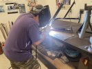
First let thank John Howard for his guidance and welding expertise. It was nice to spend the day in his shop assembling the roll bar pieces into a cohesive unit. Because he was careful about managing heat, the unit dropped right into place when I bought it back home

IMG_3906.jpeg


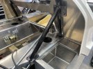
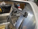
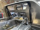
I am doing a hybrid roll bar. The main hoop is behind the FW and the crossbar is in front of the FW. I used parts from the provided six point cage to fabricate the rear hoop. I bought some more DOM for the crossbar. The two are attached through the FW via flanges made from 2” x 3/16” angle iron.

IMG_3923.jpeg


IMG_3925.jpeg


IMG_3926.jpeg


I made the hoop a bit narrower so that the feet rest close to the joint between the sponson and engine bay tub. There are two layers of vertical 1/4” aluminum plate there. I also welded on the drop bars for a cleaner look.

I made the hoop a bit taller so the top of the hoop goes up into the recess in the spider so that the view through the rear window is not blocked. I spaced the bar 3/16” away from the bulkhead to provide access to the bulkhead window frame and fasteners.

There is enough room between the spider and the top of the roll bar to add a flange that goes from the top of the roll bar, over the bulkhead and into the spider. This flange is where I will mount the front hoop connection, if I decide to add a front hoop.

I saw in other’s build logs that it was necessary to remove about 1/4” from the outer edge of the bulkhead to get it to fit inside the spider. A big part of that is the bulkhead as shipped is mounted on top of the roll bar feet. Because I narrowed the hoop and it is behind the FW, the bulkhead can be lowered down to the sponson surface, which is about 1/4”. I still had to remove some material from the sides of the bulkhead for a good fit. I just elongated the three holes on each side of bottom edge.

After I return from the GT40 Reunion, with a side trip to San Francisco and many stops in between (about five weeks of cross country RV travel), I will add 1/2” square tube wings to the roll bar.

Normally there is just a 1/8” thick aluminum bulkhead separating the interior from the engine bay.

Three problems with that: 1) Not only does it not stop the noise and heat, but it acts like a drum and amplifies the noise, 2) Anything mounted to the bulkhead will have fasteners sticking out the other side, and 3) The door striker plate has no real support.

The bulkhead will be fastened to the forward side of 1/2” tubes for support and then another layer of aluminum will be fastened on the aft side. That will create a 1/2” gap between the layers in which insulation will be added. I will use RivNuts to fasten items to the panels such as the coil, ignition box, fuse box, etc.
 
Last edited:

Chris Kouba

Supporter
Jumping all over the place while waiting for parts, answers and materials.

Today I decided to attach the rocker panels. As usual, I am totally confused.

I did find a post here that explained that the lip on the bottom needs to be cut off. Looks like some folks are putting the bottom edge inside the gap between the sponson and floor while others are fastening it directly to the floor.

My thinking is that I am not going to worry too much about the position and instead just create slots for the screws so I can move the panels back and forth an inch until I get to final fit.

I would like to know what this distance is typically.

View attachment 139624

Hey Randy,

After doing a little catch up and seeing this post, one important thing you can do before solidifying your sill placement is to get your chassis at desired ride height with your wheelbase and track accurately set, and then check your tire clearance, specifically aft of the front wheel wells. If the sills are too far forward, you will lose your ability to steer your sweet ride. I've seen it happen...
 
Last edited:

Randy Folsom

Supporter
Hey Randy,

After doing a little catch up and seeing this post, one important thing you can do before solidifying your sill placement is to get your chassis at desired ride height and check your tire clearance, specifically at the front wheel wells. If they are too far forward, you will lose your ability to steer your sweet ride. I've seen it happen...
Chris,

I am using a strap to hold my suspension at ride height, which for now is when the LCAs are parallel to the ground. I am finding that at 5.5^ caster, no camber, and the LCA with one fwd washer that the tires hit the fuel tank access plates so moving it back does not seem like an option. My wheel base is about 1/8” short of spec, so might take out those fwd washers to move it fwd but I need to double check the rear alignment first to make sure my wheel base measure is correct.

Cheers, Randy
 

Chris Kouba

Supporter
Sorry, meant make sure the sill panels are back as far as needed. I have no washers in front of the lower front A-arms.

Looks like you've already figured out you definitely don't want to move the front wheels back!
 

Randy Folsom

Supporter
Sorry, meant make sure the sill panels are back as far as needed. I have no washers in front of the lower front A-arms.

Looks like you've already figured out you definitely don't want to move the front wheels back!
Thx for the clarification. Yes, the rocker panels will likely be as far back as they will go.
 
Hey Randy ,been following ur build and its looking great.Learning alot as I read all the builds.I am going on 16 months wait so I am hoping soon.I guess the bright side is if I'm to old to build it by the time it gets here I can always sell It.:cool:
 

Randy Folsom

Supporter
Hey Randy ,been following ur build and its looking great.Learning alot as I read all the builds.I am going on 16 months wait so I am hoping soon.I guess the bright side is if I'm to old to build it by the time it gets here I can always sell It.:cool:
Ben,

It’s worth the wait. 16 months is a bit longer than usual. Are you having RCR do some of the work? It would be a shame to wait that long and then sell it.

But you are correct about selling it. You could likely recoup all your money if you sold it immediately. Any work you do on it will most likely not increase the value and might bring it down. Let me know what you decide. I have a friend that has been looking.

Cheers, Randy
 

Randy Folsom

Supporter
I decided to cut my travels short and postpone the west coast portion until the fall. Too hot and too many fires.

I had a great time at the GT40 Reunion despite it being more of a Superformance showcase. Met up with some fellow builders and learned a lot. The reunion was actually a part of annual vintage race car event. There were many iconic cars to check out.

I stopped by RCR where I spent time with Fran and Bill and also got a chance to meet Vicki. They were very generous with their time. I love seeing all the stuff they are working on.

From RCR I headed over to The Henry Ford Museum. My main focus was the Mk4 driven by Gurney and Foyt.

IMG_4032.jpeg

IMG_4031.jpeg


They also have the original Mustang. Ya gotta start somewhere.
IMG_4037.jpeg


I then drove the Gilmore Car Museum. I had never heard of it until Bill from RCR recommend it. It is fabulous. Just an amazing museum. I happened to be there on a Wednesday which is when they open the facility for car shows. Typically 300 cars, but can be as many as 700 entries. Reasonably priced food and drinks, and a live band make it totally worth the effort to get there.


IMG_4049.jpeg


I was planning to stop by the Shelby America Collection in Boulder, but it’s only open on Saturdays. Unfortunately, I will be in Sioux Falls this weekend and back in Austin by next Thursday.
 
Back
Top