Chris Kouba
Supporter
I decided to cut my travels short and postpone the west coast portion until the fall. Too hot and too many fires.
Randy,
Drop a line if you're anywhere near the NW. I need zero excuse to go on an adventure.

I decided to cut my travels short and postpone the west coast portion until the fall. Too hot and too many fires.
@ Randy, seems you are are quicker in uploding your pics and travel reportI decided to cut my travels short and postpone the west coast portion until the fall. Too hot and too many fires.
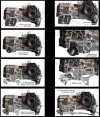
I had a great time at the GT40 Reunion despite it being more of a Superformance showcase. Met up with some fellow builders and learned a lot. The reunion was actually a part of annual vintage race car event. There were many iconic cars to check out.
I stopped by RCR where I spent time with Fran and Bill and also got a chance to meet Vicki. They were very generous with their time. I love seeing all the stuff they are working on.
From RCR I headed over to The Henry Ford Museum. My main focus was the Mk4 driven by Gurney and Foyt.
They also have the original Mustang. Ya gotta start somewhere.
I then drove the Gilmore Car Museum. I had never heard of it until Bill from RCR recommend it. It is fabulous. Just an amazing museum. I happened to be there on a Wednesday which is when they open the facility for car shows. Typically 300 cars, but can be as many as 700 entries. Reasonably priced food and drinks, and a live band make it totally worth the effort to get there.

Home
The Museum Creating Experiences that Connect People to the History, Heritage, and Social Impact of Automobiles. Unique Vehicles 435 Annual Visitors 130k…gilmorecarmuseum.org
I was planning to stop by the Shelby America Collection in Boulder, but it’s only open on Saturdays. Unfortunately, I will be in Sioux Falls this weekend and back in Austin by next Thursday.
I am guessing that you’re running a ZF transaxle. I don’t see anything from CNC performance that will work with the Quaife.Good effrot. Im running the ZF kit from CNC Performance parts. You cant beat the setup!
ZF / Quaife / RBT.... works on all of them.I am guessing that you’re running a ZF transaxle. I don’t see anything from CNC performance that will work with the Quaife.
My understanding is that it is because the MC is below the caliper. That would result in the fluid draining and overflowing the brake reservoir. That sounds reasonable, but the kit doesn’t include one for the clutch. I wonder if adding one to that line is a good idea.Why is the use of residual pressure valves seem to be common with GT40 projects?
A residual pressure valve also keeps the brake pads from retracting back into the calipers, which causes a long pedal stroke on first application. The low residual pressure in the brake line also keeps seals tight.My understanding is that it is because the MC is below the caliper. That would result in the fluid draining and overflowing the brake reservoir. That sounds reasonable, but the kit doesn’t include one for the clutch. I wonder if adding one to that line is a good idea.
Neil,A residual pressure valve also keeps the brake pads from retracting back into the calipers, which causes a long pedal stroke on first application. The low residual pressure in the brake line also keeps seals tight.
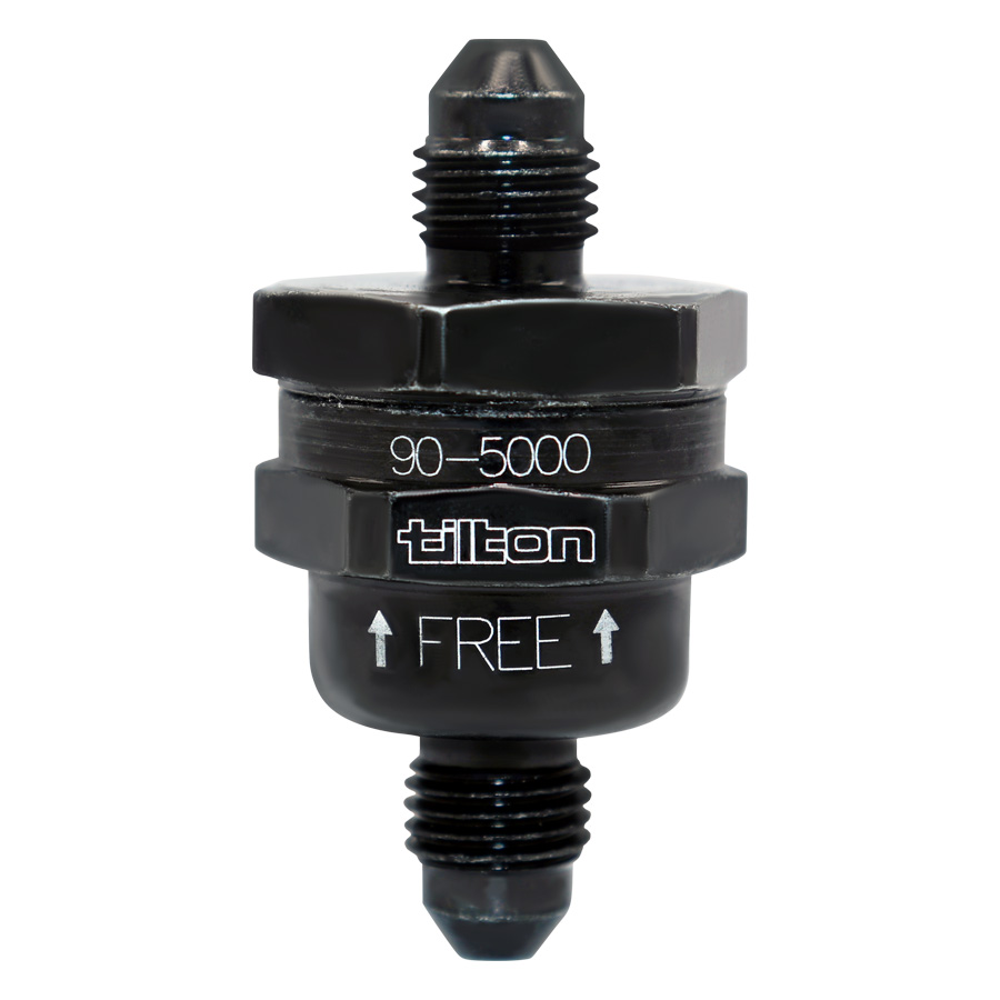
Brian,The guys have got it right about the brakes. There is not one per say for the clutch, however Tilton offers this valve for the clutch. I have purchased one and will be incorporating it in my Lola build
Flow Control Valve
Tilton's flow control valve is designed to reduce the chance of losing traction when downshifting and/or the chance of damaging driveline components.tiltonracing.com
Regards Brian
")