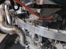
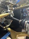
Randy's RCR40 MKI

Darius Rudis

Supporter
Are you certain you have Pulley room?
Offset axle shafts (from what I read here on forum) is okay, to a particular(?) angle.
So that being said, if you can, why-not ?
 

Ian Anderson

Lifetime Supporter
There are a few different bell housing and clutch combos so there is a possibility you have a very short bell housing hence you may be able to move the whole transaxle and engine forward.

I would resist and I would also suggest you use the bottom mounting points on the bell housing to share a lot of the loads from the engine and sharing it to the top mounts and thus the top suspension mounts and the bottom will help to stop the motor turning on the longitudinal axis and thus causing one engine mount to be stretched which is a potential fail point.

Ian
 

Randy Folsom

Supporter
Darius,

I definitely have pulley room, but not sure about how a Borla 8-Stack will fit in the rear clip’s engine cover. Also concerned the bundle of snakes might come in contact with the rear window’s aft sill to engine cover transition.

Ian,

It is definitely possible to weld another tube onto the bottom of the horseshoe. The position is perfect, but as noted above, there may be unintended consequences. Having extra mounting points would be nice and moving the center of gravity forward is generally a good thing. That being said, moving 1/2” could really mess up clip clearances. As for engine stability, after a chat with John Howard, I am going to make a set of solid engine amounts so movement might not be an issue.
 

Ian Anderson

Lifetime Supporter
Randy
On my car I ran a tuned Rover V8 and it used the standard engine mounts for a SD1 Rover which was rubber sandwiched between the two metal portions.

At Santa Pod drag strip I dropped the clutch and the left side mount pulled apart, the motor lifted and the accelerator crank mechanism caught on the rear clip holding max throttle

Slammed it into second gear at rev limiter which gave me time to turn off the key and roll to the end of the strip exiting at 58 mph

I swapped for some polyurethane engine mounts which stood up a bit better to the abuse but the motor still moved on acceleration.

transaxle in my case was a Renault UN1 unit and only had top mounting lugs

Oh and for perspective the motor was about 250 hp and torque so mild by today’s standards
 
Last edited:

Paul T.

Supporter
Randy, positioning the engine is fun with lots of things to consider such as pulley intrusion thru firewall, axle alignment and the things others have mentioned. Since your moving your rollbar another thing to consider is the crossbar to distributor clearence. Mine is pretty close positioned just below the window. Chassis mounts check the drilled hole position in the sponsons so they miss the stiffners inside.
 

Vinny P

Supporter
It looks about right where you have it I would try to gain as much clearance as you can between the water pump pulley and the firewall. I'm sure you already noticed space is a premium between the engine and RCR chassis. It's a tight fit!
 

Attachments

  • 20231113_182140.jpg
    20231113_182140.jpg
    264.3 KB · Views: 156

Randy Folsom

Supporter
Randy
On my car I ran a tuned Rover V8 and it used the standard engine mounts for a SD1 Rover which was rubber sandwiched between the two metal portions.

At Santa Pod drag strip I dropped the clutch and the left side mount pulled apart, the motor lifted and the accelerator crank mechanism caught on the rear clip holding max throttle

Slammed it into second gear at rev limiter which gave me time to turn off the key and roll to the end of the strip exiting at 58 mph

I swapped for some polyurethane engine mounts which stood up a bit better to the abuse but the motor still moved on acceleration.

transaxle in my case was a Renault UN1 unit and only had top mounting lugs

Oh and for perspective the motor was about 250 hp and torque so mild by today’s standards
Ian, it turns out that moving engine forward 1/2” from the recommended position causes so many issues as others here have pointed out. The headers hit the horseshoe cross bar, the distributor will hit the roll cage crossbar, and the engine mounting bolts will hit the internal stiffener just to name a few. But the recommended position means those lower bell housing mounts have to be cut off. I will make sure my engine mounts are not the weakest link.
Cheers, Randy
 

Randy Folsom

Supporter
It looks about right where you have it I would try to gain as much clearance as you can between the water pump pulley and the firewall. I'm sure you already noticed space is a premium between the engine and RCR chassis. It's a tight fit!
Vinny, I am going to use the recommended position. I am using a Pierburg CWA 400 electric water pump so I have plenty of clearance for that. As Paul pointed out however, the standard size MSD distributor will not clear the roll cage cross bar if the engine is moved forward 1/2” from the recommended position. Cheers, Randy
 

Randy Folsom

Supporter
Randy, positioning the engine is fun with lots of things to consider such as pulley intrusion thru firewall, axle alignment and the things others have mentioned. Since your moving your rollbar another thing to consider is the crossbar to distributor clearence. Mine is pretty close positioned just below the window. Chassis mounts check the drilled hole position in the sponsons so they miss the stiffners inside.
Paul, I had not thought about the roll cage crossbar and distributor clearance. I even I installed the firewall to check clearance and saw that I had about an inch between the plug wires and the wall so thought I was good. I forgot all about the roll cage cross bar. I will be using the compact MSD distributor since I am going with the Borla 8-Stack.

I did check the mount bolt locations. They would have gone right into the stiffeners :-(

I have also found that the bundle of snakes collectors hit the horseshoe crossbar with engine moved forward.

Cheers, Randy
 

Klaf

Supporter
You need to consider these bad boys when moving the engine forward
 

Attachments

  • IMG_7103.jpeg
    IMG_7103.jpeg
    200.7 KB · Views: 163

Paul T.

Supporter
Paul, I had not thought about the roll cage crossbar and distributor clearance. I even I installed the firewall to check clearance and saw that I had about an inch between the plug wires and the wall so thought I was good. I forgot all about the roll cage cross bar. I will be using the compact MSD distributor since I am going with the Borla 8-Stack.

I did check the mount bolt locations. They would have gone right into the stiffeners :-(

I have also found that the bundle of snakes collectors hit the horseshoe crossbar with engine moved forward.

Cheers, Randy
Another consideration, my manifold and webers are quite tall and I don't have a lot of clearance to the window. The farther back you go the less clearance. Not sure how tall Bolars are.
 

Randy Folsom

Supporter
Back to the six point roll cage. I have mocked up an idea for a hoop behind the FW. Please let me know if this looks like its going to work. I could add a diagonal brace from the side of the hoop to the sponson, but would rather not rely on the sponson for support. I might try to get the upper corner bent instead of a welded joint, but it would then encroach on the review window opening. I could also add some gussets to the corner. Thx in advance.

Behind FW Rear Hoop.JPG
 

Paul T.

Supporter
Back to the six point roll cage. I have mocked up an idea for a hoop behind the FW. Please let me know if this looks like its going to work. I could add a diagonal brace from the side of the hoop to the sponson, but would rather not rely on the sponson for support. I might try to get the upper corner bent instead of a welded joint, but it would then encroach on the review window opening. I could also add some gussets to the corner. Thx in advance.

View attachment 139598
Randy,
If you plan on tracking the car check the rules for whichever venue or club you plan on running. They all have specific rules for rollbar such as NASA, SCCA or TT. I can't think of any that let you have a welded corner. Specific angles and height from the top for rear support bars also and size of base plates. I believe most require a diagnol side brace somewhere also. Just depends on what or how involved you get in racing it.
 

Ian Anderson

Lifetime Supporter
Back to the six point roll cage. I have mocked up an idea for a hoop behind the FW. Please let me know if this looks like its going to work. I could add a diagonal brace from the side of the hoop to the sponson, but would rather not rely on the sponson for support. I might try to get the upper corner bent instead of a welded joint, but it would then encroach on the review window opening. I could also add some gussets to the corner. Thx in advance.

View attachment 139598
That looks very similar to my DAX only difference was mine was a space frame and the feet were welded to the main chassis rail which was perhaps 40 x 40mm thick wall square
 

Randy V

Moderator-Admin
Staff member
Admin
Lifetime Supporter
The welded joint you speak of is in the bar that’s normally referred to as “the main hoop”. No competition authority will approve a welded main hoop. The short distances you’re looking at there will require a very short radius to keep from encroaching on the window area. The original RCR design of bolting the bottom of the main hoop to the tub and having it hang over on top of the sponson is an odd way to support the main hoop, but hasn’t been particularly problematic in passing scrutineer inspection. The point at which the main hoop is bolted to the tub, that 4 bolt plate must have a backer plate bolted to it - effectively making a sandwich where the tub is in the center.
I recall the SCCA has a limit on how many bends you may have in the main hoop (4) with total degrees of bends not exceeding 180°.
FIA is somewhat different. Rules posted below.
If the car is not used in competition, you’re free to do whatever you like. I’ll scribble up a drawing in just a bit for my recommendation…
 

Randy V

Moderator-Admin
Staff member
Admin
Lifetime Supporter
My recommendation for a main hoop structure for street use only … ignore the line through the center of that top gusset … Your gussets should be made as a wrap around gussett of the same thickness as your tubing - see attached..
IMG_9918.jpeg
IMG_9917.jpeg
 

Randy Folsom

Supporter
Randy, thx much. I have adjusted my design. I was way overthinking it. Now I am just going to use the original hoop tucked up into the spider. The base mount and rear supports will be similar to RCR’s. I am thinking to keep the cross tube in front of the firewall and bolting it to the rear hoop through the FW.
image.jpg

image.jpg


The connection to the front hoop will be bolt in also, with two options. One will be made with two pieces of 3/4” DOM with 2-1/2” wide, 1/8” thick plate webbing. A flange on the rear will bolt to a flange on the rear hoop through the FW. The front bracket will be made from a 1-3/4” DOM split length-ways so it nests on the front hoop. The mounting studs will welded on so as not to compromise the hoop. I think with that arrangement, the connecting bars will be far enough away from my head to prevent skull fractures. For the track the connection piece will be swapped with one made from 1-1/2” DOM and 5” wide webbing.

I want to rework the front hoop such that it is closer to the spider, but not sure a long bend across the front will pass inspection.
image.jpg
 
Back
Top