
You are using an out of date browser. It may not display this or other websites correctly.
You should upgrade or use an alternative browser.
You should upgrade or use an alternative browser.
Randy's RCR40 MKI
- Thread starter Randy Folsom
- Start date
Randy Folsom
Supporter
Thx much for the information. I sent an email to Fran asking for a solution. I am hoping they will accommodate reconfiguration of D3.Randy & Vinny,
Regarding those pipes to rear clam interference. Last year, I contacted RCR because of this very same issue with my 302/363, and showed them what they could do to correct it. It's the #3 pipe on the LH side that is too high. They asked me to return them in order to put them on a car they were building at the moment. Their response afterward was that they didn't see a big issue with the minimal (no) clearance and that I could always just cut a piece out of the fiberglass because that's what they did on the originals. I then suggested that they could offer 2 different versions of these pipes. One set for those of us who want to melt the fiberglass like the originals did, and another set for those of us who don't. Oh well. So I brought mine back home, bought a piece of stainless pipe and had a welder friend reconfigure/lower that pipe. I now went from 0 clearance to about 3/4" and, with an aluminum heat shield attached to the underside of the clam, am hoping it won't be an issue.
Now don't get me wrong, I like RCR. My experiences with Fran & Bill have been exempliary and I love my RCR40 MK1. They just need to fix the damn pipes!
Rod
Randy Folsom
Supporter
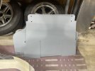
Finished undercoating the tub and front/rear panels. I used Upol’s #8 primer and Gravitex stone chip protection. The Gravitex retains some pliability for a few years but eventually gets hard like Raptor and similar bed liners. I bought the sprayer, but ended up rolling both on. The Gravitex can be painted over so if I decide to paint the exposed parts of the tub, I can cover up the Gravitex in the wheel wells.


Attachments
Randy Folsom
Supporter
Randy, It comes in black or grey, but I have not seen any mention of tinting. The expectation is that it will be top coated. I am thinking to paint the exposed tub with smooth Durabak. I’m going to test it, but my understanding is the Duraback can be brushed on and it will self level. It can also be touched up and is very durable. The problem is that once the can is opened, it only lasts a few days. From what the reviews say, resealing the can doesn’t seem to make much difference.Interesting… I wonder if you can color-tint the Gravitex like you can with Raptor?
Chris Kouba
Supporter
I hope it's better than when I asked a while (years) ago. "Just hammer in the offending tube til there's enough clearance" was the recommendation. Please share their solution when you hear from them- I'm still looking for a better one.Thx much for the information. I sent an email to Fran asking for a solution. I am hoping they will accommodate reconfiguration of D3.
Randy Folsom
Supporter
One corner assembled. Caster and camber are set per the numbers in the online build manual. Pretty easy to do if done before the wheel hub and shock have been installed. I used a digital level and referenced the front of the tub for measurements. I used an RV stabilizing jack stand to hold the lower control arm parallel to the tub’s floor.
The Stance Air Lift installation is discussed in depth via the link below. In short, I contacted Stance and was able to exchange the 120mm cups for 110mm because I had not yet installed them. It still cost me $120 for shipping. The 110mm can be installed with the shock right side up if the upper shock pickup is spaced out from the tub 1/8” and the spring cap is used for a spacer. The cap also does a better job of load distribution than the Stance provided washer.
Post in thread 'Pictures? Air lift / StanceParts'
https://www.gt40s.com/threads/pictures-air-lift-stanceparts.57810/post-595562
Randy Folsom
Supporter
The shocks are from QA1 and came with the kit. On top of the shock is a cup that uses air to compress the spring and lift the car. RCR used to sell a Hydraulic lift, but switched to the Stance Air Lift a year or so ago.Nice begining, what type of shock absober are you using ? It is a gaz tank on top ?
RCR installed my cups on the bottom, I am not sure if it makes a difference. I am not going to use my lift kit so I will be removing the Stance cup.The shocks are from QA1 and came with the kit. On top of the shock is a cup that uses air to compress the spring and lift the car. RCR used to sell a Hydraulic lift, but switched to the Stance Air Lift a year or so ago.
Attachments
Randy Folsom
Supporter
Vinny, I did not like the idea of a bucket filling with water and debris so decided to figure out how to mount them right side up. If your cups are in like new condition, stance might exchange them for the 110mm cups. Still costs $120 for shipping back to the Netherlands. I also did not like the two gallon air tank so bought a one gallon instead. It does take some modifications to make the 110mm work. The upper shock pickup needs to be spaced out about 3/16” with washers, the upper control arm ball joint bolt needs to be trimmed about 1/4” and the QA1 spring cap needs to be trimmed about 3/16”. Cheers, RandyRCR installed my cups on the bottom, I am not sure if it makes a difference. I am not going to use my lift kit so I will be removing the Stance cup.
Once I received my kit, I didn't like the thought of having a tank and all components to lift the car, I never thought about the cups retaining water. That was a good observation on your part and an excellent modification. I am going to put my lift kit up for sale to include both air tanks as I do have the smaller tank as well.
Randy Folsom
Supporter
Another corner assembled ")
Lesson learned - adjusting the lower control arm Heim joints to set the toe out is a PITA. My hat is off to the folks that set up the suspensions on these cars track side back in the day.


Lesson learned - adjusting the lower control arm Heim joints to set the toe out is a PITA. My hat is off to the folks that set up the suspensions on these cars track side back in the day.
Randy Folsom
Supporter
Well it turns out that the lower control arm Heim joints are not the best way to adjust toe. After more measurements, I found that the toe pretty much falls into place when the center to center distance to the front wheels is adjusted with the four link bars. The other side went together much more quickly.
The wheel base is 94.75” If my limited research is correct, then the wheel base is supposed to be 94.5”. Pretty close. I could probably move the front back 1/16” and move the back forward 3/16” but there would be no further room for adjustment, especially the four link bars. I have the +2 rear suspension and flares. I haven’t attempted to fit the body so hoping the flares match up.
The wheel base is 94.75” If my limited research is correct, then the wheel base is supposed to be 94.5”. Pretty close. I could probably move the front back 1/16” and move the back forward 3/16” but there would be no further room for adjustment, especially the four link bars. I have the +2 rear suspension and flares. I haven’t attempted to fit the body so hoping the flares match up.
Randy - have you got your front LCAs shimmed as far forward as possible?
The rear LCA Heims basically adjust your camber gain under bump And adjust your track width. You’ll probably be just fine with the heims adjusted to mid-depth and locked down.
The rear LCA Heims basically adjust your camber gain under bump And adjust your track width. You’ll probably be just fine with the heims adjusted to mid-depth and locked down.
Randy Folsom
Supporter
Randy,Randy - have you got your front LCAs shimmed as far forward as possible?
The rear LCA Heims basically adjust your camber gain under bump And adjust your track width. You’ll probably be just fine with the heims adjusted to mid-depth and locked down.
Thx for asking. My rear LCA has one washer and the safety washer so I can move it back 1/8” if needed. That would translate to about 1/16” spindle distance. The LCA Heims are inserted 9/16” both front and back. The UCA Heims are nearly buried with a little over 1/8” available. With the LCA level, I had no problem setting both caster and camber to the specs in the online manual.
Cheers, Randy
Randy Folsom
Supporter
The assumption is that the Lower Control Arms are level when the car is fully loaded and supported on a level floor by the tires. All measurements are taken with either the springs out, or with the spring nuts all the down, and the LCAs supported so they are level. Once the car is completed and fully loaded it gets a final alignment. Cheers, RandySorry for this stupid question but how could you make any adjustment with a car that has no wheel in contact with the flor ?
Randy Folsom
Supporter
While I wait for new engine mounts I decided to start the modification process of the six point roll cage that came from RCR.
Before:

After

I think it’s going to need to be re-powder coated
Actually, my plan is to move the rear hoop behind the firewall. I’ll need to add a few inches to the bottom of the tubes and reposition the cross bar a bit lower. The front and rear hoop connecting bars will be a box like structure made from two 3/4” tubes with a 3” web top and bottom. So total width will be about 4”. The box will have a flange that allows it to be bolted through the firewall to a flange on the rear hoop. On the front, I’ll make a split pipe flange that wraps around, and is bolted to, the front hoop. I’ll weld on studs so the front hoop is not compromised with bolt holes.
The benefits are: 1) my head will not be able to reach the connecting bars, 2) the front hoop will be closer to the A-pillars, and 3) the rear view will not be obstructed by the rear hoop. On track days I will swap out the 3/4” thick box for a 1-1/2” thick box.
Now I just need to go buy some tubing and flat stock and mock it up.
Before:
After
I think it’s going to need to be re-powder coated
Actually, my plan is to move the rear hoop behind the firewall. I’ll need to add a few inches to the bottom of the tubes and reposition the cross bar a bit lower. The front and rear hoop connecting bars will be a box like structure made from two 3/4” tubes with a 3” web top and bottom. So total width will be about 4”. The box will have a flange that allows it to be bolted through the firewall to a flange on the rear hoop. On the front, I’ll make a split pipe flange that wraps around, and is bolted to, the front hoop. I’ll weld on studs so the front hoop is not compromised with bolt holes.
The benefits are: 1) my head will not be able to reach the connecting bars, 2) the front hoop will be closer to the A-pillars, and 3) the rear view will not be obstructed by the rear hoop. On track days I will swap out the 3/4” thick box for a 1-1/2” thick box.
Now I just need to go buy some tubing and flat stock and mock it up.
Randy Folsom
Supporter
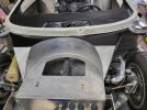
Back to engine fitment. It turns out I was trying to put the engine in too low, but I still needed to grind a little bit off the Suspension Energy engine mounts. It didn’t take much to ensure clearance so no integrity compromise.
Now I need to figure out how far forward/back it needs to go. The online manual shows 1.8” between the upper cross member and the tabs on the ZF transaxle. Which I assume is because that distance positions the output couplings directly in line with rear spindles.
My question is, if I have room to move the engine 3/4” forward and still have room up front for the front runner, should I?
Moving it back to get perfect alignment with the spindles will require cutting off some unused mounting tabs on the bottom of the bell housing. Cutting expensive parts always gives me pause. I have seen others have cut off the mounts.
Similar threads
- Replies
- 7
- Views
- 420