I changed all the gaskets of the parts making up the injection. After reassembling, the tension of the throttle cable had to be adjusted on the capstan, which was new because before, the cable acted on a small lever on the side, not through the capstan.
This forced several modifications to the bottom bracket for the end stop but also for the cable to slide without restraint. But it seems to be working. I just had to change an aviation hose that had a leaking fitting to be able to restart the engine, but impossible to redo the hose in question. I had bought dash6 hose from GT2i 2 months ago in anticipation of the hoses to be replaced, but I can't manage to assemble the fittings. When I cut the hose by any means, after having surrounded it with tape of course, it fanns out and it is impossible to compress it to fit into the fitting. It has never happened to me. So I filed a complaint to the vendor and I am waiting.
So technical unemployment on that side. I took the opportunity to mount the magnificent tank caps,
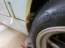
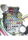
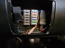
And so I went back to the front and rear covers that I dismantled to treat the few rusty steel parts, especially the false rear frame and redo the connectors, especially at the rear where I remove the badly placed additional lights.

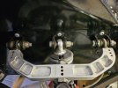
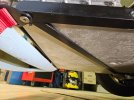
This made it easier to access the ZF DS25 gearbox. I had a leak on the studs of the rear gearbox cover. I called Samuel Pezot to find out if I could disassemble the bonnet in a horizontal position without all the bearings falling off, and then, no, you have to put the gearbox vertically. So I disassembled the gearbox with the clutch bell because they had the good idea to place 4 bolts on the outside of the bell, but 2 bolts on the inside also to fix the gearbox.
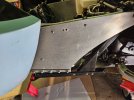
On the other hand, to access the bell you have to remove the exhausts and the crossbar that supports the gearbox, so it's quite long. I took the opportunity to repolish this beautiful machined aluminum crossbar.
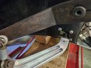
And so, I think I'm going to modify the fastening of the gearbox on the bell to access it more easily and avoid having to fall all this for a clutch for example, I'm going to try to replace the 2 inner bolts by stiuds, because in any case, the whole thing is attached well enough to the bell and the chassis.
Fortunately I took a closer look at this box because it had no oil, maybe the leak had emptied it. What is certain is that it comes from another car so what condition is it in? I sent the box to a repair shop for checking and to put a locker inside.
As the clutch is accessible, I removed the mechanism a Centerforce which is new and the fortunately I did it because the clutch disc which is also new is a standard e route disc so to replace with a ceramic. I'm going to balance the flywheel with the mechanism as well.
View attachment 139300
View attachment 139301
I ended up changing the rear caliper seals today.