SLC 001 Build

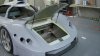
Doh! I realized after my post when I went back downstairs that thee body is in the way.

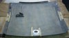
I still don't like just the 1/8" deep aluminum threading into the crossbar to secure the body. I think I'll tack a solid block of aluminum in there and drill and tap as necessary. A nutsert is also good idea and is probably more practical.

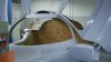
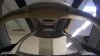
I had to re-position my body. I ended up sawing a "big" hole, laying a ?1/16''? aluminum plate over it, rivetting it in and then rivnuts into the aluminum plate. Holds well.
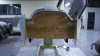
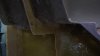
 
A little more hood action - hood hinges in place, bonding of the striker plate and strut brackets.
 

Attachments

  • 100_3145.jpg
    100_3145.jpg
    28.9 KB · Views: 794
  • 100_3146.jpg
    100_3146.jpg
    31.3 KB · Views: 974
  • 100_3147.jpg
    100_3147.jpg
    27.6 KB · Views: 957
Very neatly done....any reason you hinged it backwards rather than forward??....

My concern would be air getting underneath and you have an auto opening bonnet...
 
Thanks
Yes it would be safer to have it open the other way round, but it would be far too difficult for me to reach around the back of the opened hood..... or I would need to be (quite) a bit taller. I still need to engineer a safety catch solution, one thing at a time :) (I wish). The striker plate has a positive bonding layer of glass on top not shown in the photos.
 
Last edited:
The car is looking great Rob! I've admired the Superlite on RCR's site. Glad to see someone local is building one. Would love to come by and see it sometime if you ever have 'open house' in the garage. Now if I could just get my Pantera back together, and then get the Mustang off the jackstands and back on the road.

Cheers!
Garth
 
The radiators arrived from Superior Radiator in Detroit. Chuck and his men did a great job for a reasonable price, made them quickly and to spec. I couldnt wait to stuff them in the car so out came the die grinder right off the bat! The rads could not have been a mm wider or I would have been in some real trouble. I started the ducting work and it looks really uhh, cool ...... but I will wait till it's a bit further than the cardboard mock-up stage to post up on that. Something tells me I'll need a fender liner between the tire and the back of the rad <chuckle> BTW: The blocks of wood are there to test placement options.
Dear Rob:

I am concerned about your radiator placement. Here are two of your photos:

Robs SLC
attachment.php


attachment.php


The radiator exhausts look very close to the rear tires.

Another group of guys also built a car with mid-mounted radiators: McLaren for their 1972 M20 CanAm car. Ultimatecarpage.com describes how they handled the design:

"Following the latest Formula 1 design trend, (designer Gordon) Coppuck moved the radiators from the nose to the 'side-pods' alongside the cockpit. Widest around the cockpit area, the monocoque, with some imagination, resembled a Coke bottle when viewed from the top. The advantages of this repackaging were numerous; the mass of the radiators was much closer to the car's centre of gravity, there was no longer a need to run hot water-pipes to the nose of the car, which greatly improved driver comfort and finally the space traditionally reserved for the radiators could now be used for aerodynamic purposes. For Coppuck the main objective was to get as much of the weight as low and as close to the car's centre of gravity as possible. The resulting handling improvements were hoped to make up for the power deficit against the Porsches. For this purpose 2 inches were added to the bell-housing, increasing the wheelbase and also moving the big-block engine forward by the same amount.

"The radiators were fed by intakes just behind the widest part of the 'Coke bottle.'"

Here are a couple of photos to show what McLaren did with the radiator exhaust air:

1972%20McLaren%20M20.jpg


72-McLaren_M20-1_CanAm-DV-09_MBC_02.jpg


As you can see, the M20's hot radiator exhaust air does not contact the large rear tires.

I hope this helps.

Bassanio et Portia
 
Thank you for your input. Yes, the airflow will be restricted to a certain level by the proximity to the rear tires. Unfortunately this is a side effect of putting the largest possible radiators in a chassis and space that was not originally designed for such. The tires will be shrouded to prevent air pump from effecting exit flow. I am counting on the significant effect of the low pressure area behind the car to extract the heated air from under the bodywork. Since the path of least resistance to feed the vacuum is through the radiator ducting, the radiators should see good flow. This approach has been used before on many designs - the Corvette GTP and the LOLA GTP from which it was spawned to name but two.

In the M20 you refer to the air actually exits in a high pressure area, this is why there are air deflectors just in front of the radiator exits (to create at least a nominal low pressure zone). I would guess that the design counts more on feed pressure than exit vacuum for proper flow numbers.

Regards
(The M20 was my favorite Mclaren)
 
It looks like the radiator exits on the M20 were more to divert flow from the wheel well so as not to add to the already relatively high pressure area created by the tire rotation.
 
In the process of building a cart to roll the body around on while the chassis is getting work. The start of that work is the mid section floor and firewall 'frame' seen here. Now, how to seal the cockpit? - I do not know how others are sealing the engine compartment from the passenger compartment but this is what I have done. I glassed in a flange that will meet the external firewall surfaces, for the areas that do not meet perfectly I will seal with a seam sealer or for larger gaps a foam should work. I also think the gold heat reflective sheeting can be used to help seal some of the minor gaps.

Thoughts?
 

Attachments

  • 100_3238.jpg
    100_3238.jpg
    24.3 KB · Views: 680
  • 100_3242.jpg
    100_3242.jpg
    29.2 KB · Views: 664
  • 100_3244.jpg
    100_3244.jpg
    24.5 KB · Views: 681
  • 100_3246.jpg
    100_3246.jpg
    23.4 KB · Views: 695
  • 100_3247.jpg
    100_3247.jpg
    17.8 KB · Views: 617
Looks really good Rob! Perhaps a smallish 3/8" push-on bulb seal on your flanged areas would take up the space and look neat. Some flange trimming may be needed.
Again, impressed with your work!
 

Howard Jones

Supporter
Remember that Rob isn't pumping hot water forward. I thought about doing the same thing but concluded that it would contain too much heat in the side pods on my car. I think I am going to vent the side-pods from the bottom front via NACA ducts to allow for airflow out the back of the car and thus cool the interior of the side pods.

I really am going to have to learn how to do fiberglass as well as you Rob. I'm impressed, good work.
 
Howard,
Some pipe insulation from Home Depot along the straight portions of the coolant tubes (cockpit sides only) should prevent excessive heat in the cockpit. No real need to do extra body work.
 

Dave Lindemann

Lifetime Supporter
In the process of building a cart to roll the body around on while the chassis is getting work. The start of that work is the mid section floor and firewall 'frame' seen here. Now, how to seal the cockpit? - I do not know how others are sealing the engine compartment from the passenger compartment but this is what I have done. I glassed in a flange that will meet the external firewall surfaces, for the areas that do not meet perfectly I will seal with a seam sealer or for larger gaps a foam should work. I also think the gold heat reflective sheeting can be used to help seal some of the minor gaps.

Thoughts?

Rob - Looking VERY good as always! From my experience with my Lotus I would say that having a good seal between the passenger compartment and engine bay is critical - especially if it's going to be a street car. Exhaust/engine/gas/oil aromas (notice I didn't say smells or odors!) aren't very pleasant in the cockpit. I'm nowhere near as far along as you so I admittedly have an incomplete understanding of how the body mates to the chassis in that area but here is my thought. Rather than have a fiberglass flange resting against another flange with a foam or other seal, would it be possible to form a "U" shaped, foam lined socket that a single flange could slide into? This should eliminate any gaps created by flexing of the body while driving a possibly create a tighter seal? It would not doubt be more difficult to form. Just a thought from a novice.

Dave L
 
Is there no provision "from the factory" for sealing the cockpit from the engine compartment? Will bulb seal really get the job done?
 
Is there no provision "from the factory" for sealing the cockpit from the engine compartment? Will bulb seal really get the job done?

The bulkhead fits close to the body but there are some minor gaps due to variations in fiberglass thickness from body to body.

A bulb seal will get the job done...think about all the door jambs in your street vehicles. What do you think keeps water and fumes from getting in around the gap between the body & doors?
 
Back
Top