Rob's AK40

Hello from Rob in SW England.

I have built a few kit cars over the years, mainly Westfields, which I have competed in speed events (sprints and hillclimbs). These days with work and family commitments this is mostly limited to trackdays. I have also restored a couple of classic cars; a 1969 Triumph Spitfire (my late father's car) and a Ford Capri (reliving my youth!).

However, the dream for me was to own a GT40. I had been considering various options for a while now and finally decided to order a kit from AK in Peterborough. The plan is to use a SBF engine together with a Quaife ZF transaxle. I have yet to source either. The gearbox is no problem but I need to investigate options for the engine. I will probably go with a stroker with EFi.

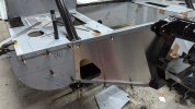
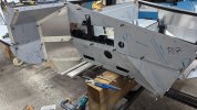
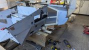
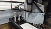
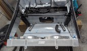
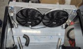
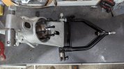
I took delivery of the chassis a couple of weeks ago together with aluminium panels, suspension and brakes. This should keep me busy for a while! Of course I had to take the standard photo of me sitting in the car!

AK Chassis.jpg
 
Last edited:
I have managed to look through all the parts I have and was impressed how well everything has been packaged by AK.

Things have been delayed with the start to work on the AK40. I was keen to finish a couple of jobs on the Capri first which has also been delayed as I'm super busy in my new job with lots of travelling.

Anyway, I finally managed to make a start on the new project. The first job is to fit the floor. In order to do this I had to turn the chassis upside down. Luckily my son was around to help me again. However, we both agreed the that it was somehow much heavier than before! Anyway, all done and time to mark out and drill all the holes.

I'm going to take it off tomorrow and be-burr everything. I'm probably not going to fit it permanently yet. I suspect I may need to add one or two inspection hatches for the coolant pipes that run down the centre of the car. I can fit the floor later in the build but it'll be easier to make any necessary modifications with it off the car.

At least all the holes will be ready when it is time to fit.

The next stage will be to flip the chassis back upright. I have partly constructed a build stand already. This needs finishing so I add details in my future update.

ak 2.jpg
 
I manage to make some more progress on the car.

I finished drilling all the holes for the floor, removed it, be-burred and sprayed some rust protector into the holes to protect the inside of the chassis. My son was called in once more and we managed to turn the chassis over again.

I have spent the afternoon trial fitting dozens of panels. What fun trying to work out which strange shaped aluminium panel went where on the chassis (no instructions)! Some of the panels fit well but many will require fettling and re-shaping. I've just taped them on for now. My plan is to work my way around the car over the next few weeks working on one section at a time to make sure all the interlocking panels fit together correctly. I'll then drill fixing holes and Cleco pin everything on. Like the floor, I may decide not to permanently fix the panels just yet, but we'll see.

ak6.jpg
ak4.jpg
 
Sorry, it has been ages since I last updated this build log.

I have been trying to get the panels on the OSF of the car marked out and fitted. The panels in this corner all fit together and overlap. It requires working in a sequence otherwise they won't fit. Each requires small modifications to line up correctly. I've held everything on with clecos for now. I still have to drill most of the rivet holes.
 

Attachments

  • AK NSR.jpg
    AK NSR.jpg
    238.4 KB · Views: 43
  • AK OSF.jpg
    AK OSF.jpg
    247.3 KB · Views: 50
  • osf panels.jpg
    osf panels.jpg
    304.4 KB · Views: 55
Last edited:
I have modified the area in front of the pedals. I got AK to make a change to the chassis in this location which allows me to mount the pedal box 75mm further forward. In the new position, the pedals still have full travel which will be important for the IVA.
 

Attachments

  • PXL_20241118_155113124.MP.jpg
    PXL_20241118_155113124.MP.jpg
    192.1 KB · Views: 55
  • PXL_20241118_155126288.MP.jpg
    PXL_20241118_155126288.MP.jpg
    214.2 KB · Views: 57
I will be using an electric water pump located at the front of the car. The pump is controlled by its own ECU which also controls the radiator fans. My engine will not use a thermostat. Instead, during warm-up, the water pump cycles, on for a few seconds then off for a few seconds. The duration of each on or off period is determined by the ECU. The pump and fans can, if required, also run when the engine is off to reduce heat soak.

I am also looking at feeds to and from the cockpit heater to be taken off the coolant circuit at the front of the vehicle (either side of the radiator). This will remove the need to run additional coolant pipes down the length of the car from the engine.
 

Attachments

  • front.jpg
    front.jpg
    293 KB · Views: 53
  • front1.jpg
    front1.jpg
    272.9 KB · Views: 55
  • water pump.jpg
    water pump.jpg
    115 KB · Views: 42
I have been having some fun assembling the rear suspension on the car.

In the picture you can see the NS rear hub assembly and the lower wishbone. Just to explain: -

- The wishbone is attached to the chassis at Point H.
- The rear hub/upright is attached to the wishbone with bar G.
- Bar G goes through a spherical bearing inside the wishbone at Point F.
- There is a bush located in a machined recess inside the hub at Point E (visible) and another at Point C.
- There is a hole bored all the way through the hub D which has a smaller diameter than the bush recesses.
- Once through the hub, Bar G goes through the spherical bearing A and is finally secured using Nut and Washer B.

Got all that!!? :p

rear wishbone - Copy.jpg


The problem I had was Bar G wouldn't fit through F. It is close though. Nothing that a little work with some Emery paper couldn't solve.

Here is a view zoomed out a bit.

rear hub and wishbone.jpg
 
What I found next was although the bar would go all the way through the hub without the bushes fitted. However, if I fitted the bushes E and C (as required) and then tried, then the bar jams about halfway through. There were two reasons....

Firstly, the recess for the bush and the hole all the way through the hub, were not quite concentric. As you can see in the photo below, there is a gap on one side (red arrow) and an overlap on the other side (yellow arrow). This was only at Bush E. Bush C was perfectly concentric.

offset bush.jpg
 
Last edited:
The other thing I found was the hole bored all the way through the hub must have been cut from either side. Where they met in the middle was not perfectly aligned. It was very, very close but enough to jam the bar due to the offset from the bush at E. Here is a photo.

Sorry, about the quality. I struggled to get my phone to focus at the right point. You can just see the issue at the red arrow.

rear hub bore - Copy (2).jpg
 
In the end, I managed to solve the problem by slightly opening up the hole all the way through the hub. I was careful not to touch the area where the two bushes fit as this is how the rear hub is precisely located. However, the exact diameter of the hole through the hub is not important so long as it is less than the bush mount point.

Ideally, I should have used a reamer to open it up slightly. As I don't have a suitable one, I got a bar of a smaller diameter than the hole, cut a slot in it and attached some Emery cloth. I attached that to an electric drill and ran it up and down in the hole a few times. It quickly did the trick and I was able to fully assemble the parts.
 

Attachments

  • rear wishbone and hub assembled.jpg
    rear wishbone and hub assembled.jpg
    449.3 KB · Views: 44
The next task was to fit the assembly to the car. This went OK with one small problem. The bushes in the end of the damper were too wide for the slot in the lower wishbone.

nitron too wide.jpg


This was actually very easy to resolve.

The bushes in the other end of the damper were narrow enough. Nitron say I can mount them upside down if necessary. In fact, doing this actually reduces the unsprung weight in the suspension.

However, it didn't look right to me. Swapping the bushes is really easy. They come in two halves and can be knocked out with a suitable drift.

nitron (1).jpg
 
Finally, I test fitted everything on the chassis.

The hubs have provision for knock on wheels. The threads are handed; right hand thread on the nearside, left hand thread on the offside of the car.

I have added the brakes too. I need a separate caliper for the handbrake - watch this space. ;)

rear suspension 2.jpg
 
Hi Rob,
Interesting to read (and see) your build. Stating the obvious, I presume you are giving feedback to Jon at AK. I'm sure he would want to be advised of any difficulties. He doesn't need grief from customers who are thousands of miles away.
I see you are in the Bristol area ..... I'm a long way from you in the heart of the Norfolk Broads. I have an MDA that I've owned for nearly 15 years. It's fitted with a highly rebuilt Ford 302 and for a laugh the car is painted in proper Ferrari Rosso Corsa red ...... we call it our one finger salute to Ferrari.
Anyway, good speed with your build ...... 2030 is looming so you need to crack on !
Best regards
Steve
 

Malcolm

Supporter
What I found next was although the bar would go all the way through the hub without the bushes fitted. However, if I fitted the bushes E and C (as required) and then tried, then the bar jams about halfway through. There were two reasons....

Firstly, the recess for the bush and the hole all the way through the hub, were not quite concentric. As you can see in the photo below, there is a gap on one side (red arrow) and an overlap on the other side (yellow arrow). This was only at Bush E. Bush C was perfectly concentric.

View attachment 145649


Hi Rob

What was your solution to the above issue please? Just received my AK rear uprights last week so will be checking to see if I have this issue too!
 
Hi Rob

What was your solution to the above issue please? Just received my AK rear uprights last week so will be checking to see if I have this issue too!

Hi Malcolm,

You maybe OK. My OSR hub was much easier to assemble. You may need to slightly reduce the diameter of bar G around the threaded end to get it through bearing F. I held the bar in a vice and used some 80 grit initially then some 300 grit. This would have been easier in a lathe, but I don't have one! Hopefully all the holes for the bushes will be concentric in your hubs.

Please drop me a message if you are struggling and I'll do what I can to help you.
 
Last edited:
Back
Top