Going to update you all with the uprights i've been working on for the last few months
Plan A was waterjet cut aluminium parts but the quotes i was getting were rather more than i wanted to pay ..
so plan B was for me to cut the exact same parts out myself (very slowly) on my DIY CNC router, which started out ok but my machine broke down after completing just 1 upright set ...
so then plan C was born, which was to make them instead from lots of left over carbon fibre and high temp epoxy. I've not gone very lightweight with them, but at this point this was the easiest way forward for me with the materials i had.
step one, 3d printed mould. due to the size of my printer this involved several segments being printed and them welded together with an old soldering iron. For the front uprights there's also some aluminium inserts prepared for mounting a steering plate and for the ball joint tapered holes. These are held in position on features in the 3d printed mould.
View attachment 140663
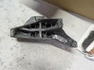
step two, add lots and lots of plies of carbon fibre and high temp epoxy, vacuum bag it and cure and room temp. demould and drill out the holes. This step puts down 80% of the total material and took me about 3 hours per upright.
View attachment 140665View attachment 140666View attachment 140667
step three, need to mould the inside surface now. I need to add stiffening ribs in some places and in other places i need a perfectly flat seat area for bolt heads to sit against. So i glue in some foam for ribs and bolt in some 3d printed shapes to form the bolt head seats. Then add lots more plies of carbon fibre, tighten the bolts in the 3d printed shapes, and vac bag it again.
View attachment 140668
step four, trim the edges, re-drill the holes, and sand it all down. make sure everything fits. Then post cure it in the oven. Used the kitchen oven for this and it took about 15 hours so i did need to ask the wife very nicely beforehand !
View attachment 140669View attachment 140662
step five, assemble
") View attachment 140670View attachment 140671
View attachment 140670View attachment 140671