Columbus Ohio RCR40

Sean Starkey

Lifetime Supporter
FEAST YOUR EYES ON THE FINIEST TIG WELDING TO EVER BE COMPLTETED IN THE NATION!!! I'll weld your exhaust as well for the measly sum of $1,000,000 a minute, (travel time is charged still). I just need to find time between the many trips I promised to SpaceX this year already to put my TIG welds on their rockets as well.

View attachment 144983

View attachment 144984

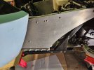
JK holy cow is TIG welding hard LOL. Turns out I had it in my head backwards on what part would be easiest/most difficult. I figured that welding the tubes together would be hard and welding each tube end to the exhaust flange would be easy... SO WRONG lol. Turns out that the large thickness of the flange compared to the tube gauge made welding much trickier and sure exposed my honestly 1st grade level of skills. Well after many days, several mistakes, and foul words... we finally prevailed.
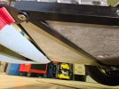
We still need to put the finishing touches on the exhaust like welding on the mufflers/tips/v-bands and O2 sensor female bungs. But at this point it is quite the relief to see just the primary exhaust system fully welded in and installed. This self built exhaust may be one of the most difficult thing's we have ever completed lol.

For those considering your own self built exhaust, some tips:
1) when welding each tube into a thick header flange, be sure to clamp down each end of the flange to a flat surface. The heat from the welds will quickly try to warp and ruin the exhaust flange. We caught this just in time and it was quite alarming lol.
2) Whatever time you budget to complete this, double it lol.

Up next after finishing the exhaust will be figuring out how to coat them (maybe jet-hot ceramic?), and then wiring everything along side finishing up the body.
Looking good. I agree that tig welding these small pipes was a big challenge. Its hard to keep everything in line, feed the filler rod and move around the pipe keeping the angle of both hands correct. I cannot confirm nor deny that a few of my welds had been ground a little with a cutoff wheel and the tig torch ran back over them to make it all look pretty.

I recommend Jet Hot coatings. They did a fantastic job on mine; the coating also helps to hide the welds a bit too.
 
Finally finished the radiator hoses. We just went to the local autoparts store and looked around their in stock selection for radiator hose bends that seemed useful. It was a better deal than just buying 90 degree universal hose. I wanted a coolant temp sensor for after the radiator to monitor real-time cooling performance. I found a nifty prepaid tube that worked out perfect. It just clears the front nostril panel, so I think minimum modifications will be needed in that area.

View attachment 138310

Holes are cut for the fog lights, turn signals, and head lights. Really happy with how they turned out.

View attachment 138311

View attachment 138312

Things are starting to look like a real car!!!

View attachment 138313

I ordered the amazon fog lights pointed out previously by Vinny (THANKS VINNY!). They worked out great, and I am excited that they aren't sealed beam units so the bulb is simply replaceable. I ended up taking off the rear covers though, as they were clearly not water proof anyways, and with them off the installation was 100 times easier as the glass lens had a lip that can cleanly butt up against the fiber glass. The old screw holes for the plastic cover could be re-purposed to mount the lens from the back side. For the money, I think these are awesome. They may be a bit dim though...

View attachment 138314
How did you mount the headlights on the backside?
 
Looking good. I agree that tig welding these small pipes was a big challenge. Its hard to keep everything in line, feed the filler rod and move around the pipe keeping the angle of both hands correct. I cannot confirm nor deny that a few of my welds had been ground a little with a cutoff wheel and the tig torch ran back over them to make it all look pretty.

I recommend Jet Hot coatings. They did a fantastic job on mine; the coating also helps to hide the welds a bit too.
I am talking with jet hot, might be a bit pricey though.... I really wish powder coating has improved further... Also we may just wrap them in header wrap for now to make sure they don't need adjusted after startup/break in tbh.
 
Last edited:
How did you mount the headlights on the backside?
I plan to fiberglass in some aluminum tabs to the clamshell to accept bolts, and 3D print some brackets to securely hold the headlight. TBD exactly what shape they become though... that's on the to do list lol.
 
Okay so the first step was to weld in the mufflers, v-bands, and tips.
IMG_4207.JPG

duct tape = TIG welds right?

IMG_4239.JPG

with the final parts welded in, it was time to finish up the mount system to securely hold the tips down.
Above you can see the rough aluminum piece I welded up. Below as well.

1741658456926.png


1741658479487.png


on both sides of the transaxle we ran "arms" down to bolt to the same brace that ties the transaxle to the rear chassis.

1741658607431.png


rear view

then came the springs a mounting tab that came with them. just simple set from Jegs.

1741658975458.png


1741659334106.png


1741659011965.png
 
final images of the tip positioning for the time being:

1741659436895.png


1741659451816.png


1741659468337.png


It took some tweaking to get the tips to be about centered and out of the way of the rear clamshell so it may open and close.

Next up is tackling the wiring and thus mounting all the lights and other devices.
Recently placed an order for the Holley dominator and a whole slew of sensors and harnesses. Holley put their products up for sale at the perfect time for that lol.
 
Not any pictures really for this update as just doing some boring stuff planning out how to wire up this car....

My objective is to "hard mount' all electrical devices prior to crimping or soldering a single harness. For example the headlight and taillights and coil packs should be bolted/taped into the car, I think.

Shown below are the coil packs with an integrated bracket. The decision is to 'remote mount" the coil packs down in the chasses of the GT40 to protect them from heat and its a convenient way to keep the spark plug wires away from the insane heat I am sure the headers will radiate. The final bolt holes for this mounting bracket we ordered haven't been drilled as the engine unfortunately will need to be pulled. Good news is that was planned anyways soon as it will need the pilot bearing and clutch bolted on. A spark plug wire kit lets us crimp the wires with either 90, 45, or straight boots as well which is helpful.

IMG_4395.JPG


A riv-nut tool is great for avoiding any annoying nuts when bolting this coil pack assembly in as well.

IMG_4397.JPG


IMG_4387.JPG


In the interest of figuring out where the ECU that will run the entire show is best mounted, I 3D printed a replica as banging around a $0.20 printed plastic chunk sounds much better than the real component lol. Holley posts .step files of the ECU case which made this simple to achieve and seems quite realistic. I really wish posting .step files online was a more common practice among more companies.

IMG_4354.JPG


Also got side tracked by trying to decide on a FR and RR tow hook for the vehicle. Hoping others can share input on what you decided to do as well. Below are a few examples that I am considering for FR tow hooks I've found. If you like your own setup it would be super helpful if you share images of how it is designed and mounted to the chasses. I can't really find much on RR tow hooks so hoping to have some input there for sure.

1744673999123.png


1744674032090.png


1744674058749.png
 
Not any pictures really for this update as just doing some boring stuff planning out how to wire up this car....

My objective is to "hard mount' all electrical devices prior to crimping or soldering a single harness. For example the headlight and taillights and coil packs should be bolted/taped into the car, I think.

Shown below are the coil packs with an integrated bracket. The decision is to 'remote mount" the coil packs down in the chasses of the GT40 to protect them from heat and its a convenient way to keep the spark plug wires away from the insane heat I am sure the headers will radiate. The final bolt holes for this mounting bracket we ordered haven't been drilled as the engine unfortunately will need to be pulled. Good news is that was planned anyways soon as it will need the pilot bearing and clutch bolted on. A spark plug wire kit lets us crimp the wires with either 90, 45, or straight boots as well which is helpful.

View attachment 146669

A riv-nut tool is great for avoiding any annoying nuts when bolting this coil pack assembly in as well.

View attachment 146670


View attachment 146671

In the interest of figuring out where the ECU that will run the entire show is best mounted, I 3D printed a replica as banging around a $0.20 printed plastic chunk sounds much better than the real component lol. Holley posts .step files of the ECU case which made this simple to achieve and seems quite realistic. I really wish posting .step files online was a more common practice among more companies.

View attachment 146672

Also got side tracked by trying to decide on a FR and RR tow hook for the vehicle. Hoping others can share input on what you decided to do as well. Below are a few examples that I am considering for FR tow hooks I've found. If you like your own setup it would be super helpful if you share images of how it is designed and mounted to the chasses. I can't really find much on RR tow hooks so hoping to have some input there for sure.

View attachment 146673

View attachment 146674

View attachment 146675
IMG_0026.jpeg


Here’s my version after going through your same struggle. I will use these for towing and transport tiedowns for the front. As far as a jacking point, the front two corners of my front subframe (also where these connect) are reinforced to support & accommodate lifting. As far as the rear I plan on using 1 or 2 (depends on how it looks) of the following types of hooks. Obviously not the middle one…

IMG_0470.jpeg
 
Last edited:
View attachment 146681

Here’s my version after going through your same struggle. I will use these for towing and transport tiedowns for the front. As far as a jacking point, the front two corners of my front subframe (also where these connect) are reinforced to support & accommodate lifting. As far as the rear I plan on using 1 or 2 (depends on how it looks) of the following types of hooks. Obviously not the middle one…

View attachment 146682

Thanks for the reply! Can you please share info/images of how the FR hooks are mounted to the chassis? Also have you planned out how the RR hooks will mount to the chassis? Transportation tie-down points are also my main goal here, forgot to mention that originally.
 
Thanks for the reply! Can you please share info/images of how the FR hooks are mounted to the chassis? Also have you planned out how the RR hooks will mount to the chassis? Transportation tie-down points are also my main goal here, forgot to mention that originally.
I’ve got a little different construction than your RCR but you can see how I did it in my build thread.
Post in thread 'Classic HorsePower Scratch GT40'
https://www.gt40s.com/threads/classic-horsepower-scratch-gt40.56682/post-590028

The rear on my frame has a couple good options for 1-2 hooks…you may have to fabricate a plate or bracket that bolts to the rear of your transaxle or where your clamshell is supported & pivots.
IMG_8905.jpeg
 
Nick, to adapt a tow hook on front, I considered that the RCR front frame made of aluminum panels will be unable to sustand the tracking effort to extract the car out of the sand box on track side.
To support the effort I added and extra frame in steel located under the front aluminum panels that I bolted on the aluminum main cell.
2 photos, one from the side, and one from outside. The steel frame is attached to bothside of the aluminum cell close to the base of the front supsension to carry the effort from the front to the aluminum cell. And the side steel bar has the function to give rigidity in the vertical direction.
I cannot make other phot now because my car is at the paint shop.
 

Attachments

  • 20241018_161557.jpg
    20241018_161557.jpg
    436.3 KB · Views: 28
  • 20241018_161621.jpg
    20241018_161621.jpg
    388 KB · Views: 37
View attachment 146681

Here’s my version after going through your same struggle. I will use these for towing and transport tiedowns for the front. As far as a jacking point, the front two corners of my front subframe (also where these connect) are reinforced to support & accommodate lifting. As far as the rear I plan on using 1 or 2 (depends on how it looks) of the following types of hooks. Obviously not the middle one…

View attachment 146682
Buyer beware with cheap tow hooks. I think it was Grassroots Motorsports that tested some of the cheap tuner Amazon tow hooks. To make a long story short…for looks only.
ZL1addons makes some good ones. I think I could hang my 66 from the ceiling with this setup.
IMG_9843.jpeg
IMG_2235.jpeg
 
Back
Top