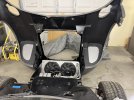
We finished mounting the radiator fans which is exciting. We mounted them using a fan shroud we built with some scrap aluminum sheeting we had in inventory.

There isn't room to offset the fan shroud due to the front nostril panel, so there isn't room to bolt the fans simply through the shroud using the convenient holes in the fans themselves. Instead we decided to bolt them using captive nuts in the channels on the top and bottom of the fans. We found that 1/4" bolts fit great just slightly shaving down two sides.

I welded tabs onto the top of the radiator to bolt the top of the shroud, and then the bottom of the shroud can simply bolt through rivnuts in the empty space on the bottom of the radiator.

Really happy with the finished product. Some buffing and powder coat will clean it up nicely as well.

There isn't room to offset the fan shroud due to the front nostril panel, so there isn't room to bolt the fans simply through the shroud using the convenient holes in the fans themselves. Instead we decided to bolt them using captive nuts in the channels on the top and bottom of the fans. We found that 1/4" bolts fit great just slightly shaving down two sides.
I welded tabs onto the top of the radiator to bolt the top of the shroud, and then the bottom of the shroud can simply bolt through rivnuts in the empty space on the bottom of the radiator.
Really happy with the finished product. Some buffing and powder coat will clean it up nicely as well.