Dave:
The tools I use are fairly basic. Thin aluminum for small pieces (like the hinge covers) is mostly cut with a small Eastwood combination shear / bender tool. The removable multiple bending blades permits creating some double folds, although that is of limited value. It does make nice cuts on thin aluminum.

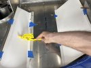
Thicker aluminum is cut with either a hand sheer or sabre saw. I use a metal blade specific for thin metal, typically Bosch from Home Depot. An important trick is keeping the speed low and letting it cut with minimal pressure on aluminum. The aluminum is firmly clamped and marked with a sharpie or masking tape.

A really handy tool is the power sander. This same unit is sold by several different companies, typically painted differently for each. Made in China. This one came from Harbor Freight. It is handy for smoothing small parts and can actually remove quite a bit of material. It is useful for getting a precise length on tubes, as well as beveling the ends.

On virtually every larger piece of aluminum a sanding block at least 18" long with 180 grit is used to assure the cut surface is straight. Cuts are typically made a 1/32 to 1/16 inch oversize to permit trimming
When ever an inside corner is present it is first drilled out, sometimes up to a quarter inch, and then the cuts made up to the round hole. Sharp corners are generally avoided since stress cracks can develop.
A hole punch is the best way to cut a round hole, but they are expensive and usually I don't have the correct size. A hole saw is often used and cut slightly undersized, then sanded to the proper size to assure a smooth opening.
Finally, working slowly and not rushing is important. (Which may explain why this project has taken years). Hope this helps.
The tools I use are fairly basic. Thin aluminum for small pieces (like the hinge covers) is mostly cut with a small Eastwood combination shear / bender tool. The removable multiple bending blades permits creating some double folds, although that is of limited value. It does make nice cuts on thin aluminum.
Thicker aluminum is cut with either a hand sheer or sabre saw. I use a metal blade specific for thin metal, typically Bosch from Home Depot. An important trick is keeping the speed low and letting it cut with minimal pressure on aluminum. The aluminum is firmly clamped and marked with a sharpie or masking tape.
A really handy tool is the power sander. This same unit is sold by several different companies, typically painted differently for each. Made in China. This one came from Harbor Freight. It is handy for smoothing small parts and can actually remove quite a bit of material. It is useful for getting a precise length on tubes, as well as beveling the ends.
On virtually every larger piece of aluminum a sanding block at least 18" long with 180 grit is used to assure the cut surface is straight. Cuts are typically made a 1/32 to 1/16 inch oversize to permit trimming
When ever an inside corner is present it is first drilled out, sometimes up to a quarter inch, and then the cuts made up to the round hole. Sharp corners are generally avoided since stress cracks can develop.
A hole punch is the best way to cut a round hole, but they are expensive and usually I don't have the correct size. A hole saw is often used and cut slightly undersized, then sanded to the proper size to assure a smooth opening.
Finally, working slowly and not rushing is important. (Which may explain why this project has taken years). Hope this helps.