Chuck and Ryan's RCR Build

Headlights

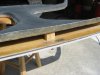
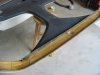
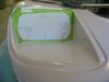
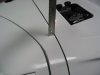
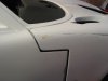
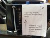
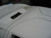
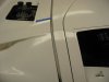
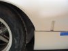
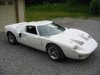
The opening for the headlights was cut, after making our usual pattern. The same pattern was used for both sides. The openings were cut small, then sanded to shape, with most of the sanding on the lower edge. As the picture shows, the lower edge started out around 3/8” but ended up less than a quarter inch from the lower edge when finished. Be careful of the top inside corner; it is tight.

We took a somewhat different approach for the headlight supports. Instead of fabricating an aluminum bracket, we opted for wood and fiberglass.

Our first experience working with fiberglass was in a somewhat unusual format. Several years ago we built a radio controlled model of New England lobster boat. The hull was fabricated from basswood bulkheads joined by stringers, then covered with a thin layer of basswood strips. The hull was sanded to its final shape. It was very light and did not seem very durable. But once it was covered with a single layer of fiberglass impregnated cloth it became remarkably rigid.

The same approach was followed in fabricating the supports for the GT head lights for several reasons. First, it is easier to cut a thin piece of plywood and sand it to the exact shape than with aluminum. Second, it can be glued with epoxy directly to the headlight opening, rather than tabbed to the inner fenders. Third, it is rigid and does not flex. Here is how we did it.

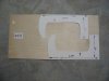
First a pattern was made. The left and right are slightly different in size, so two patterns were made.

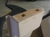
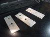
Second, we cut the supports out of 1/16” modeler’s plywood. (Midwest brand, birch plywood, 1/16” x 12 x 24). (Check you local Hobby Lobby or model railroad / airplane store). Eighth inch thick could just as easily be used and would impart a bit more strength. The plywood was carefully cut and sanded until it precisely fit the glass lenses and the openings which had been cut in the front clip. The holes to fit the aluminum frame that secures the headlight to the support bracket were then drilled.

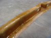
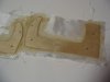
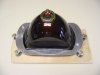
Third, the plywood was covered with fiberglass impregnated cloth, first one side, then the other Be sure to place a weight on the supports so they don’t warp while curing (make sure what ever is used does not stick) or tack it to a board. After they dried, the excess glass cloth was cut away. Some test fitting and a bit more sanding assured a perfect fit.

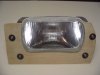
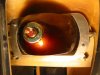
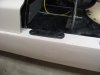
The screw assemblies, eight in all, were set up. We used stainless 10/32 x 2 inch bolts, three quarter inch washers on either side of the wood/fiberglass support tightened down with a nut. Than an appropriate spring and a brass knurled knob completed the assembly. Once the screw assemblies were secured to the support, the wood/fiberglass supports were glued in place with epoxy, running a nice bead around the inside of the head light opening. The support was carefully lined up with the opening in the clip. After holding it in place long enough for the five minute epoxy to cure, the head lights were installed.

There is no need to glue or glass the outer edges of the wood/fiberglass support to the inner fenders. Indeed it is probably better not to, since any slight body flex will stress the bracket. Indeed, with the wood/fiberglass support secured to the headlight opening the alignment will remain true and not be subject to flexing of the front clip.

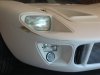
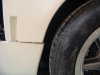
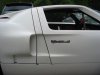
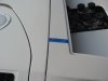
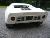
The driving lights are an inexpensive generic model available at most car parts stores. (We may replace it with a slightly larger, better quality style once we find a suitable model.) The marker lights are a Lucas, L-488, available from Finish Line. cobra, nardi, moto-lita, mini cooper, ferrari, shifter carts, parts and accessories from Finish Line. It is a dual filament, so will function both as a turn signal and a parking light. It is available in either amber or clear. Most GTs had amber, but some early cars had clear. We opted for clear to give a bit more vintage look.
 

Attachments

  • headlight1.JPG
    headlight1.JPG
    101.8 KB · Views: 877
  • Light4.JPG
    Light4.JPG
    105.6 KB · Views: 877
  • Light7.JPG
    Light7.JPG
    115 KB · Views: 882
  • LightAssembly1.JPG
    LightAssembly1.JPG
    117 KB · Views: 963
  • LightAssembly2.JPG
    LightAssembly2.JPG
    95.7 KB · Views: 934
  • LightInstalled.JPG
    LightInstalled.JPG
    137.4 KB · Views: 946
  • LightInstalled2.JPG
    LightInstalled2.JPG
    114.9 KB · Views: 1,056
Door Lever Trim Plate

Our GT has window sill release levers. An easy way to trim the slotted opening was sought. The simple solution was windshield side post plates for a Shelby Cobra. Stainless steel plates from Finish Line, www.cobraaccessories.com, will work perfectly. Once the car is painted we will likely secure them with double sided tape.
 

Attachments

  • DoorPlate1.JPG
    DoorPlate1.JPG
    75.7 KB · Views: 755
  • Doorplate2.JPG
    Doorplate2.JPG
    79.6 KB · Views: 914
Last edited:
Those Cobra windscreen escutcheon plates look right at home and finish off those door release levers nicely. Bloody fantastic idea and a great find. :D
 
Body Panels

The details of how we fitted the body panels will follow in the next three posts. I post this information with some reservations. Included are pictures of "challenges" where certain areas did not align properly requiring a bit of sanding or a bit of filler. But by the time you read this, virtually all of those issues have been resolved. They generally turned out to be little more than minor issues.

Three caveats.

First, no two cars are exactly alike. Each car will have its own little challenges. Thus our experience may be different than yours.

Second, patience is key. We have been working on the body for ten weeks and are just now reaching the last steps before sending it out for paint.

Third, think through each step before cutting or sanding anything. The panels came together remarkably well without any significant trimming. It also helps to think in three dimensions. Moving one part can affect others in ways you do not expect.

Fourth, Ryan and I have no prior experience with this sort of project, so our learning curve has likely been steeper than most.
 
Body Panels – Rocker Panels, Spider and Front Clip

Following RCR’s directions, the rocker panels were secured first. They were spaced as far back as possible. A small notch was cut out of the front lower portion of the rocker panel to assure this objective. Make sure the front wheels will clear the rocker panel when they are turned

One small metal screw was temporarily placed on each rocker panel, about five inches from the front edge, to secure it while the other panels were placed. An elongated hole was used, so it could be adjusted in and out a bit. The leading edge of the rocker panel can later be moved to achieve a better alignment with the front clip and doors. This hole will be filled in with glass filler once the final alignment is completed.

Next the spider was set in place, but not secured. Only a single 1/16” washer was used on the leading edge, which will later be replaced with a foam gasket seal. We had a reasonably good alignment between the spider and the front clip. Keep in mind our dashboard was already in place (although not screwed down) and it fits tightly inside the front lower edge of the spider, so the position of the spider was fairly well defined. Only a small amount of movement of the dash – spider was possible. No screws were used on the spider at this time so that fine adjustments could be made once the doors and front clip were placed.

It is best to have the dash in place when locating the spider, since they fit together tightly in a left hand drive car. The right hand dash is different, so we cannot comment on its affect on the spider alignment.

The forward edge of the spider B pillar was pushed tight against the fire wall so that the rear edge of the spider B pillar was about 15” from the end of the rear rocker panel. This measurement is only a guide, since final fore and aft alignment will not be possible until the doors are fitted.

The front clip was set in place, lining the rear of the wheel opening with the rocker panel. The bobbins were then adjusted to achieve an appropriate height and to assure a parallel line where the clip meets the rocker panels. Here is the interesting part, which Tom pointed out on his visit. Adjusting one bobbin by rotating it up or down slightly will cause the clip to shift left or right. By careful adjustment one can achieve a very good and uniform gap with the spider just by manipulating the bobbins.

The front corners of the spider, rear top corners of the clip, and upper front corners of the doors should all come together reasonably uniformly on both sides. Once the front clip is aligned, one can twist the front of the spider slightly from the driver’s side to the passenger side, or vice versa, to get the corners to line up with the front clip. Then a screw or two may be placed to hold the spider. Keep in mind that as one skews the front of the spider left or right, it will cause the opposite rear portion of the spider to go up or down, affecting alignment with the rear clip.

The doors can be set in place to get a rough idea about the alignment of the rear of the spider. The fire wall may have to be pulled back a bit. This will be more apparent when the doors are fitted. We ran long threaded bolts from the fire wall to an aluminum angle bracket which gave us a bit of adjustment (details appear on an earlier post, Perma Link 61, 11/13/07). http://www.gt40s.com/forum/gt40-build-logs/22083-chuck-ryan-s-rcr-build-4.html#post209590

It is amazing how tiny adjustments, perhaps a sixteenth or an eighth of an inch, can have such a significant affect in other places. Patience is the buzzword. There was lots of putting on and taking off before we got it right.

To secure the spider we installed quarter inch Nutserts, two on either side, at the base of the B pillar. This was more secure than the over-used metal screws. The spider was spaced about an eighth inch above the rocker panel with a suspension mounting plate, which made an ideal spacer. This will provide a uniform clip between the rocker panel, clips doors and B pillar. More thickness was required on the driver’s side, since the front edge of the rear clip extended a noticeable distance above the top rear edge of the spider on the driver side. (See photo). This was accomplished by lengthening the B pillar with a 1/16” thick piece of modelers plywood, fiber glassed in place, after all the body panels were fitted. (Details will be noted in a subsequent post)..

There was a small alignment problem which we could not solve by manipulating body panels. With the spider, front clip, and doors in place and aligned as best as possible, the rear portion of the front right wheel well was forward of the rocker panel about 3/16 inch. This minor problem will be addressed when we reach the sanding and body filler stage.

The gap between the front right door and the front clip, a seam about 3 inches long, was about a quarter inch plus wide; more than we want. Adding about an eighth inch of material to close the gap should not be too difficult in such a small area.

With the rocker panels, spider, and front clip in place, the doors were next.
 

Attachments

  • RearClipMismatch3.JPG
    RearClipMismatch3.JPG
    85.7 KB · Views: 864
  • SpiderSpacerPlate.JPG
    SpiderSpacerPlate.JPG
    104 KB · Views: 840
  • AlighmentFrontClip.JPG
    AlighmentFrontClip.JPG
    115 KB · Views: 798
  • FrontClipGap.JPG
    FrontClipGap.JPG
    83.9 KB · Views: 846
Body Panels, the Doors

The doors were a challenge. Without cutting or shaving anything we test fit the doors with the hinge pins removed and no weather stripping. This demonstrated that they should fit, although it would be tight. Next we hung the doors on the hinges and noted a reasonably close fit. So we ran the weather stripping all the way around. Now the doors were skewed upward slightly, with the door tops setting up a good quarter of an inch from the spider.

The geometry of the doors needs to be carefully analyzed in three dimensions. By adding washers to move the lower portion of the door hinges outward, the inner door tops can be forced downward, balancing the affect of the weather stripping.

Our car came with three spacer plates on the right side and one on the left. After a lot of tinkering, we removed one extra plate on the right and the result was a better alignment.

Slight differences in the alignment of the hinges can make significant differences at the top or back of the doors. There was lots of on and off and on and off of the hinges with different spacing to achieve the proper fit.

The weather stripping which was finally settled upon came from McMaster-Carr, part number 1120A431. It has a 5/8” round bulb. We experimented with the JC Whitney weather stripping recommended by RCR but decided against it because it results in a tighter fit than we were seeking. We also tried McMaster-Carr part number 1120A421, which has a 7/16” bulb, and found it to be a bit too loose. This was noted on a prior post.
http://www.gt40s.com/forum/gt40-build-logs/22083-chuck-ryan-s-rcr-build-12.html#post226191

The windshield must be set in place and a support stick placed to hold up the front edge of the spider to assure it is in the proper position. The weather stripping MUST be in place when the doors are adjusted.

The majority of the door adjustment is where the hinge bracket mounts to the chassis.

Here are a few tips:

1. Access the nuts on the back side of the chassis through the fuel filler opening. It is a tight fit, but with a skinny arm you can do it. Our dash was in place, so this was our only option. Without the dash in place can reach the nuts more easily, but keep in mind the dash affects alignment of the spider, so best to set it in place when aligning the spider.

2. Fabricate backing plates to use on the inside of the chassis rather than washers. (note pictures below).

3. The brackets mounted on the door which hold the hinge pin have a bit of fore and aft adjustment. Set them in the middle and make all further adjustments on the hinge bracket - chassis connection. The adjustment on the door hinge brackets should be saved as fine adjustments once everything is done, should further adjustment be needed.
http://www.gt40s.com/forum/gt40-build-logs/22083-chuck-ryan-s-rcr-build-12.html#post226095

4. You may have to enlarge the holes on the chassis. We made ours square in shape to maximize the fore – aft and up – down adjustment potential. This is another reason for using backing plates instead of washers.

5. Fabricate several spacers, both 1/16” and 1/8”, so you can experiment with different spacing. We made ours the same dimensions as the backing plates. Experiment with different thicknesses on the top and bottom hinge bolts, altering slightly the angle of the hinge. (See the picture).

6. With the hinge – chassis bolts just barely snug, set the door in place and gently adjust the door fore and aft and up and down so that it is properly positioned in the opening and – this is important – gently push the hinge upward so that the hinge is up as high as it will go to assure the hinge is supporting the door rather than the weather stripping. Also make sure the top of the hinge is snugged forward, to assure the door won’t sag downward when it is opened. Then tighten the hinge bolts with the door in place. This is a challenge, but with some gyrations one can do it.

7. The door should swing open smoothly without ‘dropping’ and return to a well aligned position.

8. We had to repeat the process many times, taking the door off and removing the hinges so different spacing plates could be tried. The single bolt hinge modification noted in the prior post made it much easier to remove and replace the door during the process!

9. Once fully satisfied with the fit, drill out two holes in the chassis through the already drilled holes in the hinge and insert a tight fitting bolt. This will secure the hinge without any further movement
 

Attachments

  • DoorHingeSpacers.JPG
    DoorHingeSpacers.JPG
    111.4 KB · Views: 722
  • DoorHinge6.JPG
    DoorHinge6.JPG
    128.7 KB · Views: 823
  • BodyPanel2.JPG
    BodyPanel2.JPG
    85.3 KB · Views: 795
  • BodyPanel1.JPG
    BodyPanel1.JPG
    101.3 KB · Views: 806
Body Panels, the Rear Clip

The rear clip was set in place, with the back end supported on jack stands. Make sure the chassis is perfectly level. Reference marks were made with a Sharpie six inches inside of the outside corner of the rear spoiler on both sides which were used to make a number of measurements, include height off the ground, distance from the spider, distance from the front of the clip, etc. These measurements were used to help determine where adjustments were needed.

Next adjust the rear of the clip right to left to make sure it is centered. Use different references, such as the location of the tires, the space between the top of the tire and the fender, etc. Due to slight variations in the dimensions of the clip, left to right, one is striving for a good visual alignment, not a precisely measured alignment. On our car it was immediately apparent that the leading edge of the clip did not align with the spider. There was about a three eighths inch discrepancy from one side to the other, resulting in a large gap on the passenger side and a tight fit on the driver side. (See picture). Indeed the discrepancy was apparent along the top leading edge of the rear clip when we measured it. Time to start sanding!

Vinyl tape was used to establish a proper straight line for sanding. A long sanding block with 80 grit paper was then used to gradually sand away the excess. Once we had sanded the leading edge of the clip so that it was even from one side to the other ( removing as much as 1/4”), the gap closed up nicely.

Once satisfied with the alignment, the hinges were installed as will be detailed in a later post.

There was one slight alignment issue on the rear clip which we could not adjust by manipulating body panels. The right rear opening of the wheel well was about a quarter inch forward of the rear edge of the rocker panel. (See picture). This will be addressed when we get to the sanding and filler stage.
 

Attachments

  • ClipRearAdjust3.JPG
    ClipRearAdjust3.JPG
    46.9 KB · Views: 687
  • AlignmentRearClip.JPG
    AlignmentRearClip.JPG
    90.6 KB · Views: 697
Very well done Chuck. I had the same issues with my body but my painter didn't do as good a job fixing the problem areas. Oh well. With your approach, you will end up with a very good alignment with nice tight gaps.
 
Good work Chuck. It is great that you are two doing this work. Another pair of eyes and additional mind helps a lot. Perfect result.


Will be interessting to se how you solved all the small issues.

Thanks
TOM
 
Excellent post Chuck. It could not have come at a better time as i'm currently aligning the body and recognise the issues you've documented - which is comforting. Can i ask - does the roof of your spider rest on the rollbar rear hoop ?

Cheers,
Simon
 

Randy V

Moderator-Admin
Staff member
Admin
Lifetime Supporter
Excellent post Chuck. It could not have come at a better time as i'm currently aligning the body and recognise the issues you've documented - which is comforting. Can i ask - does the roof of your spider rest on the rollbar rear hoop ?

Cheers,
Simon

Ditto... I'm a good 3 FULL days just in getting the spider to come close to fitting.. The rear clam shell was also cut short on the left side so I will have to build up that edge. Building up edges is a PITB and if not done right, they'll snap right off...

Chuck - I also noted that on the left side, the body lines of the spider do not align or carry the same angles of the door and rear clam shell - Is it that way on yours also?
 
Simon:

The spider is within an eigth inch or so of the rear roll hoop.(I have a rool cage, not a roll bar). It is close. Keep in mind that the rear spider is raised about 3/16" with the spacer plate (actually a suspension part) on both sides to keep the gap along the bottom of the clips, door and spider even. Without that spacer it likely would rest on the roll cage.

Also note that the left rear spider was raised about 1/8 inch as noted in the previous posts to address a fitament issue.

The front of the roll cage is about a quarter inch from the spider at the closest point. I will eventually place a small piece of hard rubber in this location to give the front of the spider a bit more support.

Picture of the spacer plate is attached.
 

Attachments

  • SpiderSpacerPlate.JPG
    SpiderSpacerPlate.JPG
    104 KB · Views: 730
Randy:

The posted pics are the "before". Some after pics are attached. Note the dimension in the picture. This was 3/8" wider (3 7/8") before any fitting was done. The 3/8" descrepancy gave rise to a couple of problems. First, it left a huge gap on the passenger side (as seen in the previoulsy posted picture.) Second, it made the edge of the rear clip set a good quarter inch above the spider on the driver side. Third, the left side tire rubbed on the clip. It all seemed a bit intimidating at first.

Once the spider was reasonably aligned, we set the rear clip on jack stands so it would 'float' in positon without the hinge hardware. I was concerned that we would have to extend the edge of the clip on the right side, which is not a good thing, as you have noted. But it became apparent that by simply trimming 3/8 off the left side we could bring things together. This was a slow and time consumming process - cut a little, refit, etc. But eventually it came together. The clip aligned nicely, the tires cleared, and the left portion of the clip was only about an eigth of an inch above the spider. By adding an eighth inch to the base of the left spider, as noted in the prior post, the issue was resolved.

Ryan has a poster of a Gulf GT hanging in his bedroom. Whenever we have a frustrating day trying to get panels to line up, I look at that picture. The alignment on the originals was often marginal at best. We seem to seek much better alignment with essentially the same panels.

It took us ten weeks to get to this point with the body - and we still have more to do. So three days on the spider is just a start!!!
 

Attachments

  • June08C.JPG
    June08C.JPG
    110.7 KB · Views: 697
  • RearClipFit.JPG
    RearClipFit.JPG
    84.8 KB · Views: 657
Last edited:
Father’ Day Weekend, 2008

Ryan and I spent the better part of the weekend working on the body. Ryan had previously sanded the entire body (about a three day job). We spent the weekend trimming panels striving for 3/16” gaps and using body filler to address the minor challenge areas. All the body panels are now fitted. About 80% of the filler work is done. We can see a light at the end of the tunnel – and it looks like the paint shop!

It always amazes me how imperfections that one does not notice while working on the car show up on photos. We thought we were 95% done, but the pics say otherwise. Another uninterrupted day and the exterior work should be done.

More details of how we got from fitting the panels to almost ready for paint will be posted later.
 

Attachments

  • June08D.JPG
    June08D.JPG
    174 KB · Views: 856
  • June08F.JPG
    June08F.JPG
    169.6 KB · Views: 815
  • June08G.JPG
    June08G.JPG
    147.9 KB · Views: 856

Rob

Lifetime Supporter
Chuck and Ryan,
I really must commend you guys for the thorough and logical approach you're taking. I always say patients and good craftsmanship pay for itself time and time again years after the effort. The payment is received every time you look at the car (or others do :-). You will certainly receive this payment. Top notch gents! Looks almost as good as mine...:shocked:...:laugh::laugh:
 
Chuck/Ryan

looks very good. One Question or tip. I also would cut out the rear clip at the opening for the license plate and mount this on spacers. This way it will help to get out the hot air where it jams itself naturaly ( at the top space of the clip).

TOM
 

Keith

Lifetime Supporter
Chuck,
No question about it you and Ryan are an inspiration. If I can only do as well when it comes time to fit the body on mine.
Please keep up the "most informative" posts.
Keith
 
Rob, Tom and Keith:

Thanks for the kind words guys. Always nice to know that the info is useful and being looked at.

Tom, as usual you are one step ahead of me. We do indeed plan to cut out that opening on the rear clip, make an aluminum plate to support the license, and use nylon spacers to support it. That is part of the "20%" we still need to do on the body. Thanks for the sharp eye.

Chuck
 
Spider Details

Several additional steps were needed on the spider before final placement could be confirmed.

1. The left B pillar was raised by fiber glassing in a 1/16” thick piece of modeler’s plywood. With the glass, this effectively raised the B pillar 1/8 inch. This helped close the discrepancy between the rear of the spider and the leading edge of the rear clip.

2. A small block of wood was expoxied in the rear center section of the spider. This simple step made the rear center section of the spider much more rigid.

3. Three areas on the rear inner portion of the spider were reinforced with a layer of fiberglass cloth: a two foot section along the center rear and two small pieces were the black liner ends. The areas are circled in the picture.

4. The windshield wiper was moved from one side to the other by RCR since ours is a left hand drive car. The switched sections had been glued in place. We added two layers of fiberglass cloth on the inside where the wiper shaft opening is located to provide more support, since the wiper mechanism is supported by the clip. The second area where the section was cut out and switched to accommodate the change in wiper location was also reinforced with one layer of fiberglass.

5. Holes for the screws along the leading edge were drilled, nine inches apart. The holes which had been used to temporarily secure the clip were filled with fiberglass resin.

6. The ends of the vertical support on the aft side of the spider interfere with the weather stripping. Accordingly a groove was filed to assure that the weather stripping would fit into place.

Once the foregoing steps were completed, the spider was reinstalled to check for final alignment.
 

Attachments

  • SpiderReinforce6.JPG
    SpiderReinforce6.JPG
    100.6 KB · Views: 848
  • SpiderReinforce4.JPG
    SpiderReinforce4.JPG
    147 KB · Views: 815
  • SpiderReinforce3.JPG
    SpiderReinforce3.JPG
    138 KB · Views: 836
  • SpiderReinforce1.JPG
    SpiderReinforce1.JPG
    124.3 KB · Views: 832
Man, you're doing an incredible job. I wish I was just begining to do my bodywork so I could make the same corrections.

Great job!!
 
Back
Top