Columbus Ohio RCR40

Sorry for the slow reply. I think you have a good idea that should work fine, but I was reminded/warned to only pull fuel from the top of the tank as designed to prevent the contents of the tank from leaving in the event of an unnoticed leak which seems like a valid concern in my opinion. I am not sure what you mean by, "While yours seems to be designed for this purpose, I can't really see how it's sealed" what do you mean exactly?
Well, I could be wrong here, but if there is a leak, it's going to be leaking when the car is running regardless. At that point it doesn't matter if the fitting is on the top or side. You don't want leaks at all....a top fitting would only prevent leaking with the car/pump off.

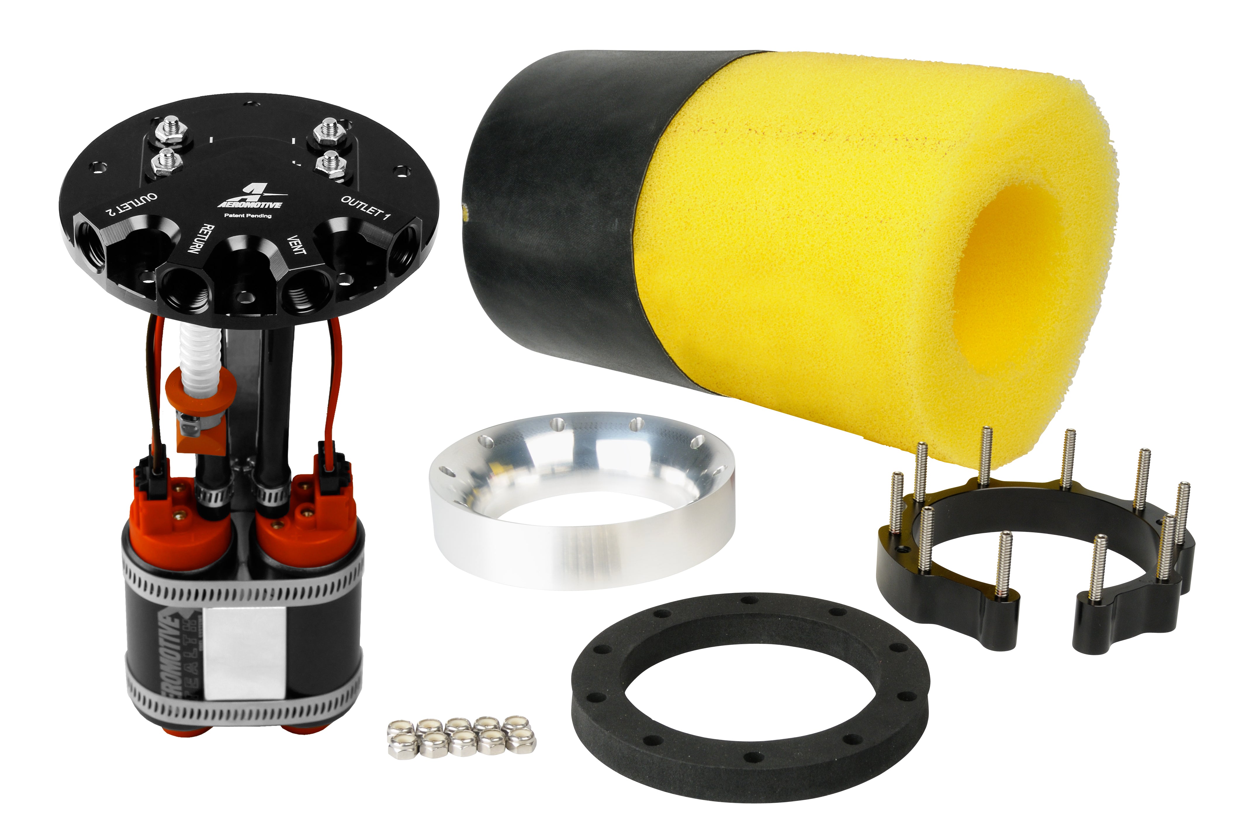
What I meant by "designed for this purpose" is your surge tank/pump appears to have been designed specifically to be a surge tank. My tank uses the Aeromotive phantom/stealth which was designed for standard fuel tank and not necessarily meant to be pressurized with fuel up to the top of the tank (other than lets say sloshing). Also your pump has an O-ring that seals against a flange. That said it doesn't address fuel around the bolts (at least I can't see anything).

While my pump doesn't use an o-ring, it uses a foam type seal (sandwich) on the top of the tank (I'll try to add pic). Aeromotive said that shouldn't leak (but again not originally designed for fuel pressurized to the top). Their suggestion for me was a viton o-ring, which would go over each of those studs on the c-ring (which goes in the tank). I also added a larger diameter return line than the feed which further limits the pressure in the surge. I still don't really like the idea and might use a fuel level gauge.

288161a9276512476cd2cff9e93f7cb9_a2965b67-1a3a-413e-8239-b64ef33cbeeb.jpg
 
Because the studs shown on the aeromotive pump run from the inside of the tank up, all the holes have to be clearanced for the bolts to run through the holes (the tank, the seal and the top all have to slide over the bolts)....Then the nuts clamp it down against the foam seal. However due to the clearance around the bolt, fuel can get around them under pressure, hence the viton o-rings inside the tank to seal off the bolt hole. I believe you have the nuts/threads on the inside of the tank, so fuel can't necessarily get around your bolt (except where it's threaded which is pretty tight). I can't fully see your design and how it's assembled, so just think it through. Consider the gasket sealant on the bolts, but I don't think o-rings are required as they might be for me.
 
Because the studs shown on the aeromotive pump run from the inside of the tank up, all the holes have to be clearanced for the bolts to run through the holes (the tank, the seal and the top all have to slide over the bolts)....Then the nuts clamp it down against the foam seal. However due to the clearance around the bolt, fuel can get around them under pressure, hence the viton o-rings inside the tank to seal off the bolt hole. I believe you have the nuts/threads on the inside of the tank, so fuel can't necessarily get around your bolt (except where it's threaded which is pretty tight). I can't fully see your design and how it's assembled, so just think it through. Consider the gasket sealant on the bolts, but I don't think o-rings are required as they might be for me.

Ok I see your point now, thanks for explaining. I will think about this and check for ways fuel can leak out of the surge tank. Thanks!
 
Well we seem to finally about be done with setting up air ducts to feed cool outside air through a fan and vents in the dash. The idea is to supply air to two "normal" vents mounted in the dash and the defroster vent for the windshield. Right now there is no way to select a defrost mode vs a "normal" vent mode, but we decided to try not adding some sort of device to "switch" the air direction. Maybe this is a mistake, but I think we will try it without a valve first. The three NACA ducts just combine into one port through the chassis.

IMG_4046.JPG


IMG_4047.JPG


Right now they look ugly, but function well. Eventually when its time to prime/paint we will be able to paint over the bottom of the front panel to clean this up a bit. Also this is tbd, but we might install some baffles to help fight unwanted water ingress, but the concern level right now with water is low because honestly hopefully the car is rarely driven in the rain.


IMG_4045.JPG


The three NACA ducts on the front panel will feed a port on the front of the chassis what will also feed an air fan. Unfortunately there isn't quite enough room to "sandwich" an air filter element in the port panel. The gasket we chose needs to be at a significant enough angle to eliminate any useful two part design for the sandwich idea to work out. Right now our idea is to simply wrap filter material around the exit of the port panel. As a result eventually I will re-design this part and re-print it with one piece as a two piece design is not needed.

IMG_4021.JPG


Here is the chillout fan bolted to the chassis. I printed a "Y" divider for the output to divide the air up.

IMG_4022.JPG


We installed two pipe "T" sections to feed the defroster vent and maintain passenger vent airflow which worked out great.

IMG_4019.JPG


These are the two ducts installed in the dash also. They fit well. My dad and I took turns sitting in the car with the fan turned on to test it out. The output seems to be plenty strong even split 3 ways currently.
 
The next project on the car is to try and tackle the exhaust... my 3d printed parts are working great to mockup a pipe layout... but it sure isn't easy to arrange the exhaust in a manner that obeys the cross over idea I discussed in this thread a while ago. It seems the middle two cylinders from each bank need to exit out the opposite bank's collector. This is at least my current understanding of how to best design the exhaust.

1731270918839.png


Here are two images of where we are at with the mockup:

IMG_4040.JPG

IMG_4042.JPG


Right now I think we can get away with only 2" and a 3" CLR bends and obviously an assortment of straight sections. I am currently making some additional parts to finalize the cross over pipes, and then it will be time to place an order for stainless tubing. Currently our solution is sending one of the two middle pipes below the other tubes to cross over and one tube above the bundle to cross. We are still struggling to find a local source in Columbus Ohio for pre-bent stainless steel 1.75" diameter tubing but we will keep looking... otherwise we have to pay shipping which is fine. It's safe to say that "bundle of snakes" is a great name for this mess LOL.
 

Attachments

  • IMG_4042.JPG
    IMG_4042.JPG
    517.3 KB · Views: 66
The next project on the car is to try and tackle the exhaust... my 3d printed parts are working great to mockup a pipe layout... but it sure isn't easy to arrange the exhaust in a manner that obeys the cross over idea I discussed in this thread a while ago. It seems the middle two cylinders from each bank need to exit out the opposite bank's collector. This is at least my current understanding of how to best design the exhaust.

View attachment 143526

Here are two images of where we are at with the mockup:

View attachment 143524
View attachment 143525

Right now I think we can get away with only 2" and a 3" CLR bends and obviously an assortment of straight sections. I am currently making some additional parts to finalize the cross over pipes, and then it will be time to place an order for stainless tubing. Currently our solution is sending one of the two middle pipes below the other tubes to cross over and one tube above the bundle to cross. We are still struggling to find a local source in Columbus Ohio for pre-bent stainless steel 1.75" diameter tubing but we will keep looking... otherwise we have to pay shipping which is fine. It's safe to say that "bundle of snakes" is a great name for this mess LOL.
Hi: Page 2 of my build log shows how the manifold looks on my car (RCR+LS7+ZFQ). It's a tight fit- including plug wires. It is entangled and both sides must be fitted/removed together.
 
Well we finally made some progress on the exhaust. One set back was we couldn't easily source 2" or 3" CLR mandrel bends in stainless tubing. We have a Jegs in Columbus that offers free shipping but we were frustrated that they don't really offer 2" or 3" CLR mandrel bends in stainless tubing. Luckily they do offer lots of 2.5" CLR mandrel bends in stainless tubing. I printed enough 2.5" CLR bends to make something work. In all fairness the pieces worked great at first, but they didn't reliably hold their shape enough to justify welding steel up. We solved this issue with a tiny bit of hot glue lol.
IMG_4108.JPG
IMG_4105.JPG


I also seriously regretted not designing any text into the pieces indicating what CLR each piece what. I ended up having to print a "template" to confirm the CLR of each piece and just write on each one what was what lol.

See below for the finest stainless TIG welding spot welds you have all EVER seen. I've been TIG welding for 105+ years so I'm clearly an expert by now. JK I am not very good, but hopefully finishing these pipes up will help that LOL. We still need to weld on springs to hold the collectors up and weld in V bands on both sides of the mufflers. The V bands are important so we can still get the pipes coated as coating the inside of the mufflers would ruin them. Things seems to fit well so far, soon we will final weld them once spark plugs and wires come in to confirm they fit ok.
One element to go still is a "hold down spring" bracket for the ends of the pipes or mufflers. We will have to get clever with mounting it to the transaxle too.
We may end up doing some sort of "remote coil mount" set up so we have options for how to run the wires.
Pipes are 304SS and the mufflers are 409SS. The local welding shop had suggestions for the best way to weld these together.
The pipes collect down to 2.5" I believe and expand to 3". The theory there is it will aid in gas extraction if you believe anything Bernoulli says but I never found any definitive proof or papers on the concept... we made the cross over theory work despite it being quite a pain. It will be worth it for that sweet GT40 sound though.
I went in 1.75" diameter tubing as from what I read it was advantageous on an NA LS motor.
P.S. for the price of a store bought mock up kit, you're better off buying and small 3D printer and downloading CAD. The parts sure did the trick!

IMG_4118.JPG
IMG_4121.JPG
 
Regarding the exhaust support bracket and springs, do you have any Karting activity near you? Karts use brackets and springs that are perfect for the task and can be bought off the shelf from karting equipment / parts suppliers
 
I'm on the fence as to if I am going to build my own headers, or just order a set from GP headers for a small block Ford. Do you have an idea on what you have invested in materials for your headers?
 
I'm on the fence as to if I am going to build my own headers, or just order a set from GP headers for a small block Ford. Do you have an idea on what you have invested in materials for your headers?
It was difficult but fun/worth it. I suggest it! Flanges to bolt to the block were $80, and about $1100 on collectors, tubing, bullet mufflers and so on. I'd suggest starting by pricing out what you can get local. It took time to confirm a decent source that had free shipping and returns available. Returns are important as we errored on ordering a tad extra tubing and the first mufflers we got didn't work out. We did it ourselves for the fun though and to have an excuse to practice TIG welding.
 
It was difficult but fun/worth it. I suggest it! Flanges to bolt to the block were $80, and about $1100 on collectors, tubing, bullet mufflers and so on. I'd suggest starting by pricing out what you can get local. It took time to confirm a decent source that had free shipping and returns available. Returns are important as we errored on ordering a tad extra tubing and the first mufflers we got didn't work out. We did it ourselves for the fun though and to have an excuse to practice TIG welding.
You can come to Strasburg and help me with mine! :) I haven't got to that point yet, everything is looking good btw.
 
Any chance a local Cbus guy can come over and "try on" your GT40 for size? I'm in the debating period and before I make the trip up to RCR a local car would be great to see in person.
 
FEAST YOUR EYES ON THE FINIEST TIG WELDING TO EVER BE COMPLTETED IN THE NATION!!! I'll weld your exhaust as well for the measly sum of $1,000,000 a minute, (travel time is charged still). I just need to find time between the many trips I promised to SpaceX this year already to put my TIG welds on their rockets as well.

IMG_4189.JPG


IMG_4186.JPG


JK holy cow is TIG welding hard LOL. Turns out I had it in my head backwards on what part would be easiest/most difficult. I figured that welding the tubes together would be hard and welding each tube end to the exhaust flange would be easy... SO WRONG lol. Turns out that the large thickness of the flange compared to the tube gauge made welding much trickier and sure exposed my honestly 1st grade level of skills. Well after many days, several mistakes, and foul words... we finally prevailed.
We still need to put the finishing touches on the exhaust like welding on the mufflers/tips/v-bands and O2 sensor female bungs. But at this point it is quite the relief to see just the primary exhaust system fully welded in and installed. This self built exhaust may be one of the most difficult thing's we have ever completed lol.

For those considering your own self built exhaust, some tips:
1) when welding each tube into a thick header flange, be sure to clamp down each end of the flange to a flat surface. The heat from the welds will quickly try to warp and ruin the exhaust flange. We caught this just in time and it was quite alarming lol.
2) Whatever time you budget to complete this, double it lol.

Up next after finishing the exhaust will be figuring out how to coat them (maybe jet-hot ceramic?), and then wiring everything along side finishing up the body.
 
Looks good to me! I talked to GP headers today about getting a set going for my SBF. I figured by the time I bought materials, then bought materials again after all of my screw ups, I would be over half way to a professional set. YouTube videos sure make it look easy!
 
FEAST YOUR EYES ON THE FINIEST TIG WELDING TO EVER BE COMPLTETED IN THE NATION!!! I'll weld your exhaust as well for the measly sum of $1,000,000 a minute, (travel time is charged still). I just need to find time between the many trips I promised to SpaceX this year already to put my TIG welds on their rockets as well.

View attachment 144983

View attachment 144984

JK holy cow is TIG welding hard LOL. Turns out I had it in my head backwards on what part would be easiest/most difficult. I figured that welding the tubes together would be hard and welding each tube end to the exhaust flange would be easy... SO WRONG lol. Turns out that the large thickness of the flange compared to the tube gauge made welding much trickier and sure exposed my honestly 1st grade level of skills. Well after many days, several mistakes, and foul words... we finally prevailed.
We still need to put the finishing touches on the exhaust like welding on the mufflers/tips/v-bands and O2 sensor female bungs. But at this point it is quite the relief to see just the primary exhaust system fully welded in and installed. This self built exhaust may be one of the most difficult thing's we have ever completed lol.

For those considering your own self built exhaust, some tips:
1) when welding each tube into a thick header flange, be sure to clamp down each end of the flange to a flat surface. The heat from the welds will quickly try to warp and ruin the exhaust flange. We caught this just in time and it was quite alarming lol.
2) Whatever time you budget to complete this, double it lol.

Up next after finishing the exhaust will be figuring out how to coat them (maybe jet-hot ceramic?), and then wiring everything along side finishing up the body.
Just blend the 'welds' with a bit of body filler... no one will then be the wiser ...LOL..
 
Back
Top