
- Forums
- GT40 Replica Manufacturers' Corner
- RCR Forum - RCR40/SLC/917/Superlite Aero
- The SLC Clubhouse
You are using an out of date browser. It may not display this or other websites correctly.
You should upgrade or use an alternative browser.
You should upgrade or use an alternative browser.
SLC 24 Howard Jones
- Thread starter Howard Jones
- Start date
Howard Jones
Supporter
Don, would the Thomas 1600 be able to sense the flow rate from the AUX pump to the swirl tank and illuminate a warning light (12vdc LED) when the main tank runs dry and the flow into the swirl tank has stopped? Fuel pressure will be about 6-8 psi with a free flow rate of about 35 GPH from the AUX pump.
If I run a warning light that's what I need it to do. This would leave me with about a gal left in the swirl tank. That would be plenty to return to the padock.
If I run a warning light that's what I need it to do. This would leave me with about a gal left in the swirl tank. That would be plenty to return to the padock.
Last edited:
These were just examples. 1600 might be a bit restrictive for your free run fuel flow.
I would call Thomas or which ever company. Tell them your fuel flow rate for switch flow size. You might need the 1300.
Make sure it is fuel rated. Vitron o-rings etc.
The reed switch has 20 Watt rated contacts. The switches usually have a normal closed contact with no flow and the other contact is open with no flow.
Howard Jones
Supporter
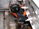
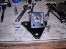
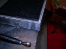
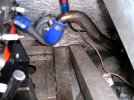
While my gearbox is off to California Motorsports for a checkout and refresh I decided to fix a couple of things while I had the motor out. The car has always had a less than optimal driveshaft angle. In order to correct it or at least improve it the engine/GRBX needs to be moved forward. I made new engine mounts and engine plate spacers to move it 11/2 inches forward. This is as far as possible and still be able to remove the alternator pulley. I believe that this will be very close to driveshaft angles of less than 2-3 degrees. I think I was closer to about 5-7 before this. Although in theory that was ok it always bugged me so I have done what I can to correct it.
Here are some pictures of the new motor mounts and the spacers. It was also necessary to reposition the electric coolant pump, the upper coolant exhaust pipe, and trim the airbox to clear the firewall. So far so good. when I get the GRBX back I will see how the rest goes and what else needs to be done.. I already know that the muffler mounts will need to be revised as well.
When the powertrain is all back in I'll post a couple of overhead before and after pictures.
The one thing that I had to think about was the driveshaft length and whether a different angle would be problematic. In theory, changing the angle does have the effect of changing the effective length, but with only a few degrees difference, the length change is less than .2 inch, and that's well within the plunge range of the CV joints. So all good there.
Here are some pictures. The motor mount on the bench is the original, and compared to the one on the car, you can clearly see the 11/2-inch forward offset.
Attachments

Last edited:
Howard Jones
Supporter
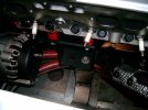
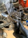
Here is the source of the little whining noise at the rear of the car. Yeah, that was not cheap. I'll add more detail to what I decide to do about this, but I am pretty sure I have found the limit of what a G50 can take. I'm pretty sure I need a 9-inch ring and pinion instead of the 7.5 inch diameter used in the G50.
I don't think this was a lack of lubrication failure. I drained nearly 5 quarts out of the gearbox when I removed it from the car. Gearlube was Redline 75W90 NS GL-5 Gear Oil. It was NOT burned. Smelled and looked just like the new stuff in another container.
Ideas of what this looks like? My opinion is too much torque. But it is a layman's opinion. I have no special expertise in gearbox design or metallurgy.
Attachments

Last edited:
flatchat(Chris)
Supporter
Crown wheel flex?Here is the source of the little whining noise at the rear of the car. Yeah, that was not cheap. I'll add more detail to what I decide to do about this, but I am pretty sure I have found the limit of what a G50 can take. I'm pretty sure I need a 9-inch ring and pinion instead of the 7.5 inch diameter used in the G50.
I don't think this was a lack of lubrication failure. I drained nearly 5 quarts out of the gearbox when I removed it from the car. Gearlube was Redline 75W90 NS GL-5 Gear Oil. It was NOT burned. Smelled and looked just like the new stuff in another container.
Ideas of what this looks like? My opinion is too much torque. But it is a layman's opinion. I have no special expertise in gearbox design or metallurgy.
Chris Kouba
Supporter
Porosity defect(s) in the casting?
Neil
Supporter
I would not think that this would be a casting.
Howard Jones
Supporter
Ya, I'm nearly certain that the pinion gear is a forging as well as all the other gears. I think the divots in the teeth were caused by contact point fatigue failure resulting in cracking and causing large sections of the gear to shear off. There was some similar damage to the ring gear as well. It's just not as pronounced. My understanding is this is common when a gear set is overloaded. I know a guy who understands this stuff and when I showed him the picture he said it was continuously overloaded but not overheated.
A LOT of information here:
Bottom line? I need bigger gears. Ya........... we knew that............................so does Porsche. That's why they went to a 9-inch R&P.
I'm thinking of putting the fully repaired and rebuilt G50 into my GT40 and taking out the R21 Renault. It should be done or nearly done as I write this. The GT40 has a 350HP 302 SBF so it should be very happy with that much power.
Oh and this GRBX has an upgraded and very stiff CMS crown wheel plate installed on it. See post # 1180 for a picture of it. It should not have flexed.
Last edited:
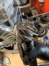
The explainations on the video are reflecting reality, but in your case I would think, to a combination of problem. Because of the erosion pattern on the pinion that is not equal or similar on all the circonference of the pinion, I would check if the pinion axis is not missalign with the shaft on it is assembled. This could explain why you have so much erosion on one side and nothing on the rest of the pinion. The explanation of the phenomena on the video is clarifying what is the consequence on a too high pressure between gear. But the origine, for me is that your gear had a missalignement of axis. Normally it is minimum because those parts are forged and machined after, but an excess of tolerances going all in one direction could be possible. Check the rest of the pinion, if it could still talk, I am not shure because it is soo damage.
Howard Jones
Supporter
Jean, The pinion bearing was spun, and the bearing bore had to be repaired. Cause or effect? I don't know what happened first. Thank you for the comment; every little bit of information is useful, but I do agree that the damage isn't symmetrical. Maybe the bearing spun and misaligned the gears, causing the rest of the gear damage?
Attachments

Last edited:
Howard Jones
Supporter
I placed a deposit with California Motorsports for a 6-speed 996 Turbo GRBX. We will change the gear ratios to better suit my wishes and install a WaveTec TBD as well as some strengthing pieces and an internal spray oiling system. We also finished the repair and rebuild on my G50. I may put it into my GT40. I really liked the way it shifted and the gear ratios so I believe it would be perfect for my 350HP SBF in my GTD.
I guess I will be spending some money on GRBX;s this coming year...................Ya, this hobby isn't cheap................ However the more I learn about GRBXs the more I understand why good ones are so expensive to do correctly. As far as GRBX's go, there's no cheap way to run 550HP in track cars on slicks and drive them hard.
I guess I will be spending some money on GRBX;s this coming year...................Ya, this hobby isn't cheap................ However the more I learn about GRBXs the more I understand why good ones are so expensive to do correctly. As far as GRBX's go, there's no cheap way to run 550HP in track cars on slicks and drive them hard.
Attachments

I have no real experience with automotive gearboxes, but from my industrial gearbox and pump experience, some of that damage looks very like cavitation damage. I would only expect this type of damage to occur if the gearbox was over-filled, or perhaps if the pinion area became flooded under acceleration, deceleration or cornering. Any of these could lead to overheating and cavitation due to filling of the mesh with oil. High performance industrial gearboxes are often lubricated by pump with spray-bars delivering the correct quantity of oil for lubrication and cooling in a spray mist. If they are overfilled or the sump level is too high it leads to cavitation and overheating due to excessive oil entering the mesh. In a car, especially with such high performance and high g forces I wonder if this could be a contributing factor. So I wonder if and how automotive racing designs control oil delivery to the pinion. I'll let you judge if the above makes any sense, but good luck!
Howard Jones
Supporter
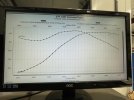
Rodger at California Motorsports told me that the damage we were seeing was the usual damage that resulted from applying very high torque numbers through the 7.5-inch R&P used in a G50. "This is why Porsche went to the 9-inch R&P's" He has "seen this before with high power V8's".
Here is the torque curve for this motor. It really never makes less than 450 ft/lbs from 3000-past 6000 rpms and over 500 from 4200-5400. So once the tires get hot, at corner-exit, I can leave it in 3rd gear, roll the corner, get excellent traction, and just add full power until I want to shift and keep accelerating. This is an almost continuous torque overload for the small R&P in a G50.
Dave, The idea of cavitation would have never occurred to me. Thank you for that information. I really don't know what to say on that. I think I'll ask my oil industry engineer down the street about that as well as mention the idea to Rodger when I talk to him next time.
Attachments

Last edited:
Darius Rudis
Supporter
How do you Measure and Adjust the REAR Caster?Rodger, I was reading all my books again and trying to understand the rear "caster". Among them are, Alan Staniforth-Competition car suspension, Carroll Smith's books, and Len Terry and Alan Baker-Racing car design and development. Nobody uses the term "rear caster" But somebody used the term "rear upright incident angle" or something like that. So I will now not use "rear caster" anymore because I don't think it exists except as a description of misadjustment.
So I think the Corvette "0" spec is meant to eliminate misadjustment errors and establish a preliminary basis for further adjustment of toe. The more I think of it, the more I believe you hit the nail on the head. If the "ball joints" can only move in a perfectly vertical plane then the only thing that affects the rear toe is the toe link, its adjustment and it's geometry. Given that, it seems to me that "caster" on a double a-arm rear suspension really has no effect. The term really does not have any meaning in this application.
Another way to think of this is the two A-Arms on the rear are fixed at all three pivot points. Two inboard and one on the upright each. None of them swing on an arc and only move vertically. Therefore they can't CHANGE the toe from its at-rest setting. ONLY the toe link geometry can do that. There is no DESIRED "rear caster".
Mounting the toe link on the A-arm at one end and the upright at the other prevents the toe link from moving in an arc as well. Thus resulting in a stable toe setting throughout the suspension travel. Every race car pic I found does it this way including the green RCR SLC. Pretty much done and dusted on this question for a race car.
I think I will try and set the rear toe as close as possible to 0. The above texts do warn that too much neg rear toe will cause oversteer so it should be kept to a minimum with a preference on preventing ANY positive toe. That will also produce oversteer but much more dramatically.
Dave, since my SLC is a track-only car and I am running R7 Hoosiers I need to run a lot more camber. The Hoosier guy I talked to wanted me to run at least -2 and as much as -3.5 depending on tread section temps and tread wear. It is currently set to -2.5 F and -2.0R. I ran -.75 on my GT40 when it was a dual use car and then went to -.5 as I returned it to street only use. Runing a lot of camber on the street will really effect tire life. I view about -.5 as a street car maximum.
Here's a C8 specs.
Claimed stock C8 alignment specs
10-19-2019, 12:38 AM
So they claim :
The stock curb alignment specs (a full tank of fuel with no passengers) alignment specs :
FRONT
Caster: 7.4 +/-0.6 deg
Camber: -0.5 +/-0.6 deg
Sum toe (left + right): 0.10 +/- 0.20 deg
REAR
Caster: 0 +/-0.8 deg
Camber: -0.5 +/-0.6 deg
Sum toe (left + right): 0 +/- 0.20 deg
Track Alignment Specs
FRONT
Caster: 8.0 deg
Camber: -3.0 deg
Sum toe (left + right): 0.1 deg
REAR
Caster: 0
Camber: -2.5 deg
Sum toe (left + right): 0.1 deg"
Of particular note is that the rear caster specification is tightened from 0-(-.8) to absolute 0. This would confirm the information Dave posted above. Also, you can see that GM thinks -.5 degrees of camber is correct for a street car. I suspect this is to preserve tire life.
I love this forum. Always a good thoughtful discussion. I couldn't get by without it.
Front caster process is with turn plates... but REARS?
p.s. Comfortable with the Rear Toe and Camber settings, just looking for assistance on REAR CASTER.
As per RCR:
Attachments

Neil
Supporter
Drop a plumb bob line from the center of your top bearing and measure the offset of the lower bearing, then use trig to calculate angle based on that reading and the length between top & bottom bearings.How do you Measure and Adjust the REAR Caster?
Front caster process is with turn plates... but REARS?
p.s. Comfortable with the Rear Toe and Camber settings, just looking for assistance on REAR CASTER.
As per RCR:
Howard Jones
Supporter
There is no such thing as rear caster. To measure caster at the front, the front tires need to be turned, as in direction change, a known amount and THEN caster can be calculated. Since the rear tires do not turn, as in direction change, there is no calculation possible as to caster. There is no rear caster.
The term rear caster is sometimes wrongly described to be the angle determined by the line drawn through the upper and lower pivot points of a rear upright. BUT, this is not caster at the rear. By the way, everything I have been able to find in writing on this subject tends to recommend the rear upright is usually designed straight up and down on bespoke single-seater formula cars.
So I have gone to describing this rear upright variable as "rear upright pivot point angle" not rear caster. Neil's method will calculate this for you very accurately.
If you center the rodends in the brackets on the top and bottom chassis a-arm mount points you will be fine as a start point. If you need to move any of the four be sure to correct the other like a-arm on the other side an equal amount in the same direction. My SLC has been like this since the beginning at the rear. At the front, the same "center the rod end in the U brackets" method will get you about 6 degrees pos caster, That's where mine is and it drives fine. Just be sure to make both sides the same.
Last edited:
Neil
Supporter
For details, see my last post about suspension geometry in "Wings & Keels".There is no such thing as rear caster. To measure caster at the front, the front tires need to be turned, as in direction change, a known amount and THEN caster can be calculated. Since the rear tires do not turn, as in direction change, there is no calculation possible as to caster. There is no rear caster.
The term rear caster is sometimes wrongly described to be the angle determined by the line drawn through the upper and lower pivot points of a rear upright. BUT, this is not caster at the rear. By the way, everything I have been able to find in writing on this subject tends to recommend the rear upright is usually designed straight up and down on bespoke single-seater formula cars.
So I have gone to describing this rear upright variable as "rear upright pivot point angle" not rear caster. Neil's method will calculate this for you very accurately.
If you center the rodends in the brackets on the top and bottom chassis a-arm mount points you will be fine as a start point. If you need to move any of the four be sure to correct the other like a-arm on the other side an equal amount in the same direction. My SLC has been like this since the beginning at the rear. At the front, the same "center the rod end in the U brackets" method will get you about 6 degrees pos caster, That's where mine is and it drives fine. Just be sure to make both sides the same.
Similar threads
- Replies
- 12
- Views
- 875