Have a look at drawing 2103. External.So went to add in the flange on the part that goes over and around the tunnel and have run into a discrepancy in my cad model.
The question is, do I make the central tunnel 2.75” internal width or external width. I’d previously had it as an internal dimension, but now I can’t remember why I decided that. It’s been so long since I drew that part of it.

You are using an out of date browser. It may not display this or other websites correctly.
You should upgrade or use an alternative browser.
You should upgrade or use an alternative browser.
Ryans Group Ten GT40 build - Body 5.
- Thread starter Ryan Love
- Start date
slowly, inch by inch.
Radiator roughed in. Added the front clip hinge mounts after the discussion the other day.
Not how the radiator sits higher to allow the brake cooling ducts to run underneath.

Im still trying to work out the radiator connections on the back side. The hoses cant go out the ends like they did on the later MK I nose as the brake ducts are there.
I also think there was an oil cooler on the starboard side of the car. This style of radiator was in the car when they left FAV in the UK and landed at SAI.

Not sure if this is 104 or 103, wheels are chrome/silver where as 104 was shipped with black wheels. So i suspect this may be 103.

Car below is 104, as the mirror matches with what it has fitted. note the black wheels.

Lower outlet for the oil cooler on the end will be tight.

That's if I decide to connect it.

Still have to fix a few more details, but its getting closer.

Radiator roughed in. Added the front clip hinge mounts after the discussion the other day.
Not how the radiator sits higher to allow the brake cooling ducts to run underneath.
Im still trying to work out the radiator connections on the back side. The hoses cant go out the ends like they did on the later MK I nose as the brake ducts are there.
I also think there was an oil cooler on the starboard side of the car. This style of radiator was in the car when they left FAV in the UK and landed at SAI.
Not sure if this is 104 or 103, wheels are chrome/silver where as 104 was shipped with black wheels. So i suspect this may be 103.
Car below is 104, as the mirror matches with what it has fitted. note the black wheels.
Lower outlet for the oil cooler on the end will be tight.
That's if I decide to connect it.
Still have to fix a few more details, but its getting closer.
One thing to note, the front brake cooling was re-arranged to pull heat from the radiator to help cool and preheat the brakes to keep them from cracking. That was one of the solutions they came up with since they would basically shock cool almost, and be thermo cycled so much from hard brake to long fast run amd hard braked again. By keeping them slightly warm, this cycling was prevented.
If you were to be running carbon brakes and dics this would help you brake better and lesson the overall wear.
Modern brakes have much better tempering and better heat cycling characteristics. Just a thought if you are going for true originality.
If you were to be running carbon brakes and dics this would help you brake better and lesson the overall wear.
Modern brakes have much better tempering and better heat cycling characteristics. Just a thought if you are going for true originality.
Bugger. Just looking at some more photos, and it looks like the vertical flange above the ductwork that I have just removed, was a mistake on my part and it was just a trick of the light and the photo that made it appear to be flush with the top of the SHS tube. Ah well. Backwards before we go forwards.
I have been slowly chipping away at it in between other jobs.
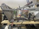
I have spent a bit of time on the red bit in this picture that closes off and directs the air into the duct on the front/side of the spare tire recess.

Then some more time trying to sort through the lower air dam and ducting below the radiator. Many hours going between photos trying to find the right angles. I think just about all of these parts pictured below have been changed in some way since the post on the 2nd of June

you can see that the brake ducting still does not line up 100%, so there was obviously a difference between the early P chassis 1000 to 1005 that had the triangular lower ducts and that which was on 103.

P1005 on the right, not sure which car is on the left.

I have spent a bit of time on the red bit in this picture that closes off and directs the air into the duct on the front/side of the spare tire recess.
Then some more time trying to sort through the lower air dam and ducting below the radiator. Many hours going between photos trying to find the right angles. I think just about all of these parts pictured below have been changed in some way since the post on the 2nd of June
you can see that the brake ducting still does not line up 100%, so there was obviously a difference between the early P chassis 1000 to 1005 that had the triangular lower ducts and that which was on 103.
P1005 on the right, not sure which car is on the left.
I am still trying to confirm the radiator dimensions. It is of a different design to the standard MK I unit. It has an oil cooler on the starboard side of the construction.
It is also located closer to the front axle centre line. Not I don’t have the horizontal section of tube that the typical MK I front end has. So it’s around 4” rearwards of where yours is Morten. This should also allow a bit more height.
It is also located closer to the front axle centre line. Not I don’t have the horizontal section of tube that the typical MK I front end has. So it’s around 4” rearwards of where yours is Morten. This should also allow a bit more height.
It all helps. You never know what detail will be relevant and remaining from one iteration of the chassis to the next.
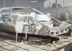
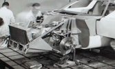
Those photos like either GT101 or GT102.
The vertical rear suspension pickups are still square/straight. I do notice that they continue down too but do not pierce the lower chassis reinforcement that forms the perimeter of the front floor. Some of the later prototype chassis certainly had these parts go all the way through the outer box section. Not sure if they needed extra clearance for a suspension modification or test.
Dry sump tank is still in the nose.
You can see the oval shaped hole through the B pillar in the first photos, but none of the ventilation ducting on the front of the chassis.
The forward section of the brake ducts in the lower nose section appears to be inverted in comparison to what was done on 103 and 104.
103 at Daytona in 65, as this was the only race it ran using #73.


Lower brake duct seems to taper downwards, and be lower than the under tray. Will have to amend my cad again.
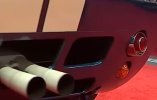
This is GT103. It has a different grill over the radiator to 104 which was taped on with black tape. GT103 also has a different internal rear vision mirror to 1GT04. Any ideas on the single head light / spotlight in front of the radiator would be helpful. There is a single screw that undoes from the front at the 9 o'clock position near the mount, that holds the chrome ring on.

1964 spec lower air intakes.

Judging by the tape lines on the light cover above, I suspected this is #12 at Lemans in 64, which would have been GT104 Driven by Attwood and Schlesser, however it has the canards added, so have no idea as things obviously changed and the two photos above and below were not on the same day.

Those photos like either GT101 or GT102.
The vertical rear suspension pickups are still square/straight. I do notice that they continue down too but do not pierce the lower chassis reinforcement that forms the perimeter of the front floor. Some of the later prototype chassis certainly had these parts go all the way through the outer box section. Not sure if they needed extra clearance for a suspension modification or test.
Dry sump tank is still in the nose.
You can see the oval shaped hole through the B pillar in the first photos, but none of the ventilation ducting on the front of the chassis.
The forward section of the brake ducts in the lower nose section appears to be inverted in comparison to what was done on 103 and 104.
103 at Daytona in 65, as this was the only race it ran using #73.
Lower brake duct seems to taper downwards, and be lower than the under tray. Will have to amend my cad again.
This is GT103. It has a different grill over the radiator to 104 which was taped on with black tape. GT103 also has a different internal rear vision mirror to 1GT04. Any ideas on the single head light / spotlight in front of the radiator would be helpful. There is a single screw that undoes from the front at the 9 o'clock position near the mount, that holds the chrome ring on.
1964 spec lower air intakes.
Judging by the tape lines on the light cover above, I suspected this is #12 at Lemans in 64, which would have been GT104 Driven by Attwood and Schlesser, however it has the canards added, so have no idea as things obviously changed and the two photos above and below were not on the same day.
Any constructive feedback would be most welcome. I've been looking at the photos of GT103 and GT104 for ages now and I am not sure if I have missed anything obvious or if I have done a good job of matching the dimensions.
I've used the drawings that were in GT40 Uncovered to get the main dimensions for the parts associated with the radiator support structure. These drawings appear to be based on the designs used for the first 5 production chassis, so its been a task that involves making an educated guess as to what the prototype structure was. I have tried to keep as many hard points and angles as I can, whilst only adjusting edges, fold directions and angles to align with the photos of 103 and 104 that I can find.
I have created some repositories of images for the various chassis here if anyone is interested in checking out the details of the early cars.
Pinterest allows you to link and store hyperlinks to various online images in your own collections, so all or most of these images are from various public locations on the web.
Any help would be appreciated.
Regards Ryan
Any constructive feedback would be most welcome. I've been looking at the photos of GT103 and GT104 for ages now and I am not sure if I have missed anything obvious or if I have done a good job of matching the dimensions.
I've used the drawings that were in GT40 Uncovered to get the main dimensions for the parts associated with the radiator support structure. These drawings appear to be based on the designs used for the first 5 production chassis, so its been a task that involves making an educated guess as to what the prototype structure was. I have tried to keep as many hard points and angles as I can, whilst only adjusting edges, fold directions and angles to align with the photos of 103 and 104 that I can find.
I have created some repositories of images for the various chassis here if anyone is interested in checking out the details of the early cars.
Pinterest allows you to link and store hyperlinks to various online images in your own collections, so all or most of these images are from various public locations on the web.
Any help would be appreciated.
Regards
This is looking really impressive! You are going to end up with a better version of 103. Are you going to paint it the same color?Time for another update, if only to remind myself of where I am up to as its been a few weeks since I have been able to touch the project. As mentioned elsewhere I think I have decided on a prototype to focus on. I was continually finding that I was looking at photos of different cars and getting conflicting details as they are all slightly different. I have decided to focus on GT103 as it was specked for Sebring in 1965. Since making this decision I have done a fair bit more research on the car, some of which many here have helped with.


I have created a number of albums of online images relating to some of the early GT40 chassis on pinterest if anyone else is interested.
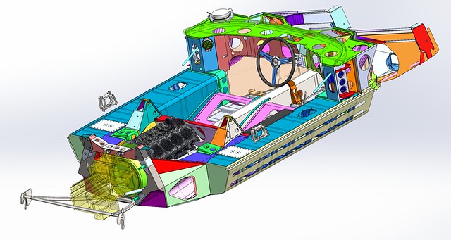
After that I have been modifying my CAD model to capture some of the unique elements of GT103 that don't appear in latter chassis. Hopefully they are apparent in the screen grabs.
I still need to work out the floor details.

Details of the ductwork around the spare wheel area either side of the radiator. Changes to the dash and side sill tops. Lots more work to be done around the radiator yet.

Looks like I might have been working on the orange panel on the side of the radiator last. This is likely the latter production panel as its too long for the prototype nose length.
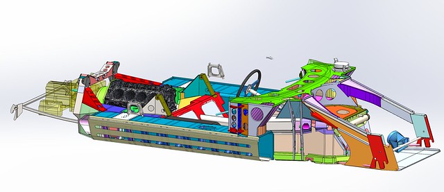
Oval shaped holes in the A pillar/door pillars. extra holes around the rear support hoop area as well as a two piece part to support the rear horse shoe shaped part.
Changes to the steering wheel, I like the one that's in GT108 for some reason.
Still need to amend the rear upper trailing link towers as they are different on 103
Cheers Ryan
Probably as per Sebring 1965, so that it is different to the real 103 which is in its Daytona 65 livery.
The real 103 currently seems to have different wheels to what it wore in 65. The throttle linkage is also different in its current arrangement. in 65 they used a linkage that was similar to the Cobra where it came into the turkey pan on the left rear intake behind #8. The GT40 cable normally comes in between #6 & #7.
The whole front of the car as well as some of the other details on the bodywork is different as it was converted to MK I spec in Will Wonders ownership.
Following on from James and Alistair's excellent build thread I am now trying to work out what parts i need to collect for the rear slam catches at the top rear edge of the roof.


This one below is of 104, as the refill is above the B pillar duct.

This one is cool as its one of the only photos I have seen that shows the oil going in. This is 103 as the mirror is on the windscreen and the quick connect fitting is in the B pillar duct not above it.

This one below is of 104, as the refill is above the B pillar duct.
This one is cool as its one of the only photos I have seen that shows the oil going in. This is 103 as the mirror is on the windscreen and the quick connect fitting is in the B pillar duct not above it.
JimmyMac
Lifetime Supporter
The very same haunch design and slam catches as ours.Following on from James and Alistair's excellent build thread I am now trying to work out what parts i need to collect for the rear slam catches at the top rear edge of the roof.
This one below is of 104, as the refill is above the B pillar duct.
This one is cool as its one of the only photos I have seen that shows the oil going in. This is 103 as the mirror is on the windscreen and the quick connect fitting is in the B pillar duct not above it.
Last edited: