
Randy Folsom
Supporter
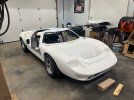
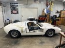
Rod,My spider does not fit to the cage for crap. It is not symmetrical from right to left. I was afraid the spider was way off, but took to measuring the cage to the chassis first.
(1) The two overhead front to rear bars of the cage are shifted towards the driver and are not in the center of the chassis.
(2) My front hoop has a bit of fore/aft curve along the top "straight" part, especially on the passenger side
(3) Passenger A pillar cage point is more outboard on the bracket while the drive A pillar cage point is centered in the bracket.
(4) I needed to trim the spider at the bottom of the A pillar due to cage interference.
What is really odd is the overhead bars are shifted toward the driver while the front hoop of the cage seems to be shifted toward the passenger side of the car. I do not believe any of this is the end of the world or has any functional impact. It certainly does not look right from the front of the car.
View attachment 140074View attachment 140073View attachment 140072View attachment 140071
I decided to cut off the front hoop and move the rear hoop behind the FW. There were just too many challenges with retaining the front hoop and many advantages to moving the rear hoop. I am retaining the ability make and install a front hoop, but it will be significantly different.
If you want I can share the plans for the rear hoop I made in Fusion 360.
Cheers, Randy


.JPG")
.JPG")
.JPG")
.JPG")
.JPG")
.JPG")
.JPG")
.JPG")
.JPG")
.JPG")
.JPG")
.JPG")
.JPG")
.JPG")
.JPG")
.JPG")
.JPG")
.JPG")
.JPG")
.JPG")
.JPG")