Electric Water Pump How to.

Ian Clark

Supporter
Mid engine cars are just more complicated compared to front engine/rear drive or rear engine rear/drive. Even the OEMs have challenges with engine compartment heat, reduced lifespan of soft parts in the engine compartment, plumbing, cooling, wiring, a/c and tool access for routine maintenance.

If you are prepared to do the best you can with the information available (especially GT40s.com) AND prepared to potentially take it apart because of an unforeseen packaging issue or systems malfunctioning, you are on the way to building an exceptional car.

Regarding the ability to heat the cockpit, there's no shortage of hot water in a GT40 replica or original.

Most of the conventional wisdom about heater function in hand built cars comes from the likes of hot rods, restomods and sports cars based on front engine front radiator layouts. Not much help there, just pay attention the height of your header tank and bubble bleed lines.

In GT40 applications you have several options based on your chassis manufacture provisions and your choice of drivetrains for routing coolant pipes between the engine, radiator and heater.

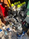
Although "individual circumstances may vary", the simple mechanical waterpump with thermostat, bypass plumbing, adequate rad fans and proper fan controller combination should give no trouble cooling the engine or heating the cockpit. Although the accessory drive is more complex and space to the firewall almost non existent.

Back to the topic of this thread:

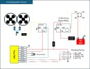
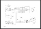
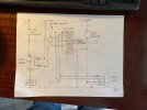
The use of a remote mounted electric water pump reduces accessory drive complexity and provides more space to the firewall. The electric water pump on/off/variable speed and radiator fan(s) on/off/speed have to be managed by the ECU or other controllers. A mechanical thermostat is redundant in this setup.

With proper control of the water pump and rad fans to engine will warm up quite quickly if the car is happy to idle for a few minutes. Then you have hot water available...

The tight packaging of the engine compartment, under dash area and plumbing routes will narrow your choices as to where to run the heater hoses. The direction of flow however is always the same: from the engine to the heater to the radiator inlet. It's preferable to mount the heater shutoff or variable flow valve outside the cockpit, reducing the number of really hot water leaks.

The system itself is not difficult, it's the packaging layout and leaving yourself access for future maintenance that's the challenge.

Cheers
Ian
 

Pat

Supporter
I wanted to jump in and see what people are doing to route coolant hoses from the block. I have a Dart 302 block and have an WP adapter plate with 12AN male outlets. Should I run long sweep 12 AN 90s? Is this large enough to go to the EWP (using the recommended Pierburg). I’m trying to figure out fittings and hoses for whole system while everything is out of car in floor.

Attached picture has straight 12AN-12AN for now.
 

Attachments

  • IMG_5191.jpeg
    IMG_5191.jpeg
    530.6 KB · Views: 164

Klaf

Supporter
I have a ford 351 and a Davies Craig electric water pump with the adaptor plate rather than mechanical pump. Where should I connect the T stat bypass too? Should it be plugged?
 

Bill Kearley

Supporter
Take water from right behind the thermostat on the intake and run a line to the intake side of your pump. Up load a pic of the pump your using, there site has a few different ones !
 

Klaf

Supporter
Wiring question:
The Davies pump uses ground to activate the fan relay. This uses pin 85. They suggest jumping pin 86 to 30. Which brings 12 volts thru pin 86
image.jpg

The problem I’m having is the diagram for the vintage air wiring uses 12 v thru pin 85 and I think ground is 86 via the trinary switch.
image.jpg

How should this be wired? Should a second relay be used and run them in parallel?
 

Randy Folsom

Supporter
I have been trying to figure out the EWP coolant system electrical setup. Below is my first attempt. I am not any sort of wiring wizard so there are bound to be issues or concerns.

I am using the Pierburg CWA 400, the TinyCWA controller from Techmotive and a relay with up to a 10 minute delay to keep the system running after the car is turned off.

The fans will be turned on and off by the TinyCWA controller, but when on the highway, I would like to override the controller and turn the fans off since there should be plenty of air coming through the radiator.

My thinking is to put a thermo switch at the output of the radiator that will cut power to the fans when the coolant is cooled sufficiently. I don’t know what that temperature is.
 

Attachments

  • Cooling System Circuit.jpeg
    Cooling System Circuit.jpeg
    281.2 KB · Views: 46
  • IMG_0919.jpeg
    IMG_0919.jpeg
    115.2 KB · Views: 63

Ian Clark

Supporter
Hi Randy,

Have you checked in the instructions for hi/low temperatures settings for the fans? If so (most likely it does) then you have no need for a fan off over ride switch.

Cheers
Ian
 

Randy Folsom

Supporter
Hi Randy,

Have you checked in the instructions for hi/low temperatures settings for the fans? If so (most likely it does) then you have no need for a fan off over ride switch.

Cheers
Ian
Ian,

Thx much. I am new to EWPs and rear engine cars with the radiator up front so please bear with me. I don’t know where the high/low temp reading is coming from that you referenced. I am guessing a temp sender in the intake manifold. If so, then I assume the fans will run when the engine is hot regardless of how much cooling is done by ambient air at the radiator. If there is a temp sender on the radiator, I am guessing it is located in one of the radiator’s side tanks. That water should also still be hot. My thinking is to place the sender on the output since this should be after the water has been cooled by the radiator.
 

Howard Jones

Supporter
My advice would be to put all the temp sensors in the intake manifold. The coolant temp target is the coolant temp at the hottest location in the complete system. That's the top of the engine, heads, and by extension, the intake manifold.
The fan on temp would be selected to be about 10F above the system target nominal temp. So if you wanted the coolant in the heads to be 185F, for example, then turn on the fans at 195F and have them go off at 175F. This way at normal running speeds airflow will keep the coolant at the target temp (185F) and the fans will not come on.

I would like to see an override switch so that the fans can be manually turned on at the drivers discretion. Lots of good reasons for this. I also think it would be best to split the protections between the two main loads, The fans and the pump, separate the circuit breakers of each, Power the controller of the pump from the pump circuit breakers, and the fans from the fan circuit breaker. Place your override fan switch in the fan relay control circuit.

I'll read up on the tiny controller a bit and see if I can draw you a circuit diagram for the whole system.
 

Ian Clark

Supporter
Hi Randy,

The Hi\Low temperature setting is a function of the Tiny Waterpump Controller and responds to the temperature input from your sensor(s) on the engine, radiator.

Additionally the A/C pump relay can to trigger your rad fan relay. It does help the cooling system to stay ahead of engine temperatures due to low air flow through the radiator, much like an override switch would do if you were stuck in traffic with A/C on.

On re reading my reply above, and in agreement with Howard, a manual override is required. Modern production cars don't have one but the original GT40s did.

Cheers
Ian
 

Howard Jones

Supporter
I left out the run on controller. If you have a manufacturer document on it I can look it that and include it if you like and it will work. Frankly, I don't think you need it. Just let the car cool down a bit before you turn it off.
 

Attachments

  • image_123927839.JPG
    image_123927839.JPG
    325.3 KB · Views: 52

Randy Folsom

Supporter
I updated my Cooling System Circuit diagram before I saw John Howard’s drawing so will likely update it again.

I added the A/C Trinary switch, pump and fan indicator lights, manual override, and radiator outlet temp switch with a potentiometer. The Tiny CWA has to go to Pin 85, while the delay relay and manual override go to Pin 86, so needed to add another relay.

The primary temp sensor is the one on the manifold connected to the TinyCWA controller

The overrides that force the fan on are the A/C Trinary switch and the manual override switch.

My hope is that the radiator outlet switch will only cut off the fan when the A/C is not running and the coolant temp coming out of the radiator is low enough to not need the fan, i.e., driving on the highway on a cool day. I will likely move the radiator outlet temp sensor as described by John Howard.

For sure John Howard’s diagram is easier to follow :)

1737860242116.png


1737860448751.jpeg
 
Last edited:

Randy Folsom

Supporter
Wiring question:
The Davies pump uses ground to activate the fan relay. This uses pin 85. They suggest jumping pin 86 to 30. Which brings 12 volts thru pin 86 View attachment 144407
The problem I’m having is the diagram for the vintage air wiring uses 12 v thru pin 85 and I think ground is 86 via the trinary switch. View attachment 144408
How should this be wired? Should a second relay be used and run them in parallel?
Not an expert, but my understanding is it doesn't matter if 85 or 86 is grounded. Likewise 30 and 87 are interchangeable. Convention is grounding 85. Some signal inputs are positive voltage so if you're trying to stay with the conventional pin 85 input, then 86 is ground, but you can just as easily connect your positive input to pin 86 and use 85 as ground. Not sure what to recommend, but I suspect there are standards to make future trouble shooting possible.
 

Ian Anderson

Lifetime Supporter
Question.
You are driving down the highway on a warm day.
You have airconn on
Will your fans be running?

If so why as surely natural airflow is doing the work and no fan is necessary.
I can only see the fan not running if there is a road speed sensor that stops the fan above say 25 mph

I never had this problem as never ran aircon

Ian
 

Randy Folsom

Supporter
Another attempt. I used John Howard’s drawing as a starting point. This one is a bit less complex. I have not figured out how to turn on the water pump without going through the controller. I think need to apply 12v to the grey/red and ground to the grey/black wires on the pump. I am going send an email to Technomotive. I also did away with the idea of a separate circuit/temp sender to turn off the fans. I think it best to rely on the controller. I still need to add the status indicator lights.

1737886637875.png
 
Back
Top