Chuck and Ryan's RCR Build

Randy V

Moderator-Admin
Staff member
Admin
Lifetime Supporter
Hi Chuck - Many thanks for posting the pictures and text to go along with it - as usual you guys are doing great work...

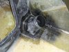
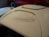
One thing that I am also planning on doing is to support the top of the spider to the inner panel as you did - but - I'm planning on cutting and forming a block of wood to fit a wider area.
You "may" have a problem with that small wooden block making an imprint (showing through) on top of the spider over time.

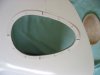
I can tell you right now, I can (and did) deform the spider without heat and just hold it there for a week (I did this to get the "Z" out of it) and then release it.
It will hold it's shape for quite a while without support.
Mine is gradually over the last couple of weeks - going back to the "Z" as it came out of the mold.
What all that means in fiberglass terms is beyond me - but I picked mine up almost a year ago...
 
Chuck Smith:
The RCR Spider is a two layer spider with a very nicely done inner layer ( sand and paint). The design of the inner layer is exactly like on the originals ( I think the only other replica copiing exact the original design is SPF with their steel roof). You can see this in post #259 in middle two pictures.
The compartment built by this two layers is open towards the rear, where it attaches to the firewall and is closed by it and a fitting weatherstripping around.

Chuck, Randy,
i purchased a lightweight ( 250 gramms/liter) 2 component epoxy foam system ( MCMC Products: Epoxy Foams). It is a non pressure building foam expanding to 4 times it volume. Why non pressure. if you check the curing versus the expansion curve you will see that it has totally expanded before it cures. So as long there is enough open space where it can "crawl" to no pressure is builded up ( the rear opening of spider between the outer and inner panel is perfect for this). After curing and some baking at 45-50°C this foam gets very solid. As it also is used in building boats it also have non water sucking properties. I plan to do this with the spider mounted and the doors adjusted and closed (drilled already some 1 1/2 " holes in the inner panel to be able to fill it with the liquid epoxy foam), so that there is no risk of missaligning and fixing the spider in a position which will not fit and difficult to correct afterwards.
I calculated the volume of the spider with app 11 - 12 liters (app3 gls) and ordered 4 liter of this foam. Will do this as soon my rear clip is finished. I already did some test parts, works great , no comparisson to PU foam out of the bottle.

TOM
 
Last edited:

Keith

Lifetime Supporter
Chuck,
I just noticed that it appears that you have "cut out" the NASA ducts on the fenders. Do you plan on using them as fresh air intakes?
Keith
 
Keith:

Although the ducts on the fender are opened, they are only for looks. No plans to use them as air intakes since the dash side vents hook to the AC unit. Of course, that could change . . . .

The vent at the top center of the front clip, which would normally vent to the top dash vent, has not been cut out. Doing so would create a path for water to go places we don't want water to go. So we will likely leave it closed and paint that area flat black. But I can't decide for sure since not opening it up just does not look quite right. Suggestions????
 

Keith

Lifetime Supporter
I believe that I will leave the center duct closed also. However, I am thinking that I will open up the ones on the fenders to duct fresh air in, I am not too sure where though. I have been looking into using blast gates like Bill D. did, but putting them down by the fuel tank inlets.
If I can't figure something out I will just leave them as they are since the car will be black it will not be obvious.
Keith
 
Gurney Bubble Installation

After some debate the “race car” look was decided upon. We liked the idea of the stainless steel button head screws, which look like rivets, holding down the bubble. It would add another focal area of interest.

1. The lip around the bubble was uniformly trimmed to ¾ inch. Then a pattern was made so that the screw holes could be located evenly around the perimeter approximately two inches apart.

2. A chalk line was snapped down the center of the car to provide a point of reference. The bubble was located so that it was exactly parallel to the chalk line.

3. Holes were drilled in the bubble for 6-32 button head stainless screws.

4. A pattern was made for the hole. Two of the holes were drilled through the roof and small screws temporarily placed to secure the bubble and make sure the location was right before we cut the big hole. The opening was then cut exactly ¾” inside the outer lip of the bubble using our pattern..

5. The roof of the door has an inner liner. There is a gap between the liner and the roof which needed to be filled. Two screws were placed to secure the bubble, one on the forward and one on the aft end. This flexed the roof slightly to assure a snug, even fit around the entire perimeter of the bubble. Epoxy was then used to fill the gap between the liner and the roof, making sure to avoid any on the two temporary screws. (A piece of wax paper between the bubble and the roof prevent the bubble from inadvertently being glued in place).

6. A coat of body filler was applied around the opening between the inner and outer panel which was then sanded to provide a smooth transition between the outer panel and the inner liner when viewed from the inside.

7. Nutserts were placed in the door to secure the 6-32 button head screws. The button head screws were temporarily placed, pending final painting and finishing.

A thin rubber or foam gasket will be placed between the bubble and the door when it is installed after the car is painted. The bubble will remain removable, although I don’t anticipate ever removing it, unless Ryan grows another inch or two!
 

Attachments

  • BubbleInstal1.JPG
    BubbleInstal1.JPG
    116.9 KB · Views: 594
  • BubbleInstall5.JPG
    BubbleInstall5.JPG
    99.4 KB · Views: 599
  • BubbleInstall2.JPG
    BubbleInstall2.JPG
    100.4 KB · Views: 582
  • BubbleInstall6.JPG
    BubbleInstall6.JPG
    88.3 KB · Views: 567
  • bubbleinstall8.JPG
    bubbleinstall8.JPG
    93.5 KB · Views: 625
Hi Chuck,
My Idea was to extend the duct back a little to create the look of an open vent without actually opening it up fully. I intend to make a piece that can be attached to the front clip, then blend in the vent opening so that to the casual observer it looks open. It's only if you examine the hole closer that you will see that it's closed further in.
 

Attachments

  • CCF26062008_00000 [640x480].jpg
    CCF26062008_00000 [640x480].jpg
    11.9 KB · Views: 546
I meant this drawing...!
Doing too many things at one time. Should have known I can't multi task..
 

Attachments

  • CCF26062008_00000 [640x480].jpg
    CCF26062008_00000 [640x480].jpg
    13.5 KB · Views: 600
Martin:

Good idea. Would you fab it out of aluminum? Seal it to make it water tight?

May give this a bit more thought. Looks like with a bit of effort a good solution could be found.

My problem is I am anxious to get it to the painter and I am looking for corners to cut. Guess I need to make sure I don't cut corner's we will later regret.

Thanks for the suggestion. I may pursue this one further.

Chuck
 
I cut all 3 NACA vents open on my car. I did not put a filler on the back side of any of them. In all three cases water intrusion is not an issue because the other side of the vent is not in a dry area anyway. the only down side of not having a filler is if you stand in just the right place you can see daylight through the vent. I thought about a filler like you are proposing but I figured I could glue that on at any time so that became a B list item.
 

Dutton

Lifetime Supporter
...Guess I need to make sure I don't cut corner's we will later regret.

Chuck,

If there's ONE thing you haven't done to date, that would be cutting a corner. Your build clearly documents that!

Similar to Jonathan, I opted to open up the ducts before painting; much easier to do it before than after the paint is applied...

Best,

T.
 

Dutton

Lifetime Supporter
Chuck,

This pic just arrived from friend Alan Snelson. Interesting touch...
 

Attachments

  • Vent.jpg
    Vent.jpg
    24.7 KB · Views: 937
I've opened up and boxed in the ducts before. The centre duct only had a box that was only a couple of inches long due to space restrictions. The side ducts box was around 200mm(8") long.

Inside of the box section was painted black, with just a slight groove put between it and the original body.

In my opinion opening up the ducts give the front clip a lot more depth and detail. The cheap alternative is to paint the faces black and stick some mesh on the front.
 

Attachments

  • DSC_2645 [640x480].JPG
    DSC_2645 [640x480].JPG
    100 KB · Views: 683
  • DSC_2646 [640x480].JPG
    DSC_2646 [640x480].JPG
    86.2 KB · Views: 681
  • DSC_2650 [640x480].JPG
    DSC_2650 [640x480].JPG
    83.5 KB · Views: 679

Rob

Lifetime Supporter
Chuck,
I cut mine open, for the fenders ....glassed in hose mounts from a pair of ducts, and left the center one open to the back lip of the front clip, which I painted black. Turned out nicely and will do it this way again.
 

Attachments

  • P1090621.jpg
    P1090621.jpg
    58.3 KB · Views: 774
I opened all three of mine and glassed in ductwork for the two smaller ones. At some point I may run them into the car for ventilation, but to Jonathan's point, that is a B list item.
 
In retrospect, I don't know why opening that vent was even an issue. No reason not to open it up. As noted, it is a wet location regardless. Thanks for the wake up call.

Got home. Removed the front clip. Taped off the opening. Cut it out. Sanded the edges. Put the clip back on with a piece of black paper behind to see how it will look when we later paint the back syrface flat black. Job done.

Hope to get all the body prep done this weekend so we can take it to the painter next week.
 

Attachments

  • VentFront1.JPG
    VentFront1.JPG
    87.6 KB · Views: 698
  • VentFront2.JPG
    VentFront2.JPG
    90.7 KB · Views: 685
  • VentFront3.JPG
    VentFront3.JPG
    77.8 KB · Views: 741
Back
Top