Mike Pass
Supporter
Here is an article I put together a while back for the GT40 Enthusiasts Club magazine. I have finally got round to posting on here.
Chassis torsional stiffness
I am not a structural engineer but here is my amateurs attempt to understand chassis rigidity, especially the GT40 chassis in it’s many variations.
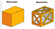
There are two main types of chassis – monocoque and spaceframe. Monocoques are boxes made from sheet material. Spaceframes are lattices made from steel tubes.
The idea of a chassis is to be a rigid structure to which various components can be attached – mainly suspension, engine and transmission. In order for the suspension to operate correctly, the chassis should be as rigid as possible so that when the car hits a bump or dip, the suspension moves rather than the chassis flexing.
Chassis torsional stiffness can be measured by bolting the front suspension pick up points to a solid concrete floor and placing a pivot at the centre of the rear of the chassis between the rear suspension pickup points. A long bar attached to the rear pick up points can then be loaded with heavy weights at a known distance from the pivot. This will twist the chassis. The twisting or torsional load can be calculated by multiplying the distance of the weight from the pivot by the size of the weight. The angle through which the chassis is twisted can be measured using a dial gauge to measure the deflection or more accurately by attaching a laser pointer aimed at a white board at a known distance. The angle can be calculated from the distance moved divided by the distance from the pivot of the measuring device. This number is the sine of the angle that the chassis has been twisted. The chassis stiffness is usually quoted in lbs.ft per degree (pounds times feet per degree) or N.m per degree (Newtons times metres per degree). So, if you have a strong concrete garage floor, a cheap laser pointer, a few resin anchors, some lengths of rigid steel and some known heavy weights then you can test your chassis, make changes and then retest to improve stiffness.
Below is a list of chassis and their torsional stiffness figures. I cannot vouch for their accuracy as they were collected from various sources on the internet. However, they are a reasonable indicator and give some interesting comparisons. Most steel frame GT40 replicas will be in the same range as the GTD Lola T70 replica and the Ultima.
**List of chassis and their stiffness in later post ( file to big for one post!
So, what makes a chassis torsionally stiff?
Answer. What it is made from and how that material is arranged.
Flat plate has almost zero stiffness but if bends and folds are put into it then it gets stiffer. Angle is a step forward and channel even better but still not good enough. If the sheet steel is made into box sections or round tube then it is very much improved.
See Pic. 1 Section stiffness
Obviously, whilst the solid section is rigid the weight rules it out for car purposes unless you have a need for a 3 ton GT40.
A monocoque chassis is made from sheet steel boxes. A spaceframe chassis is made from box or round tube joined up into a lattice.
See Pic 2 Monocoque compared to spaceframe
The original GT40 chassis and most modern cars are made from pressed sheet steel panels which are spot welded together to make boxes. These boxes are then attached to other boxes to make up the chassis. The boxes are often unusual shapes to fit occupants, doors or other items. It is easy to make a strong chassis from huge chunks of steel but a car chassis also needs to be as light as possible so the design of the chassis needs to provide the maximum stiffness for the minimum weight.
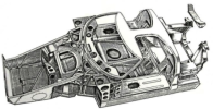
The original GT40 chassis were made from sheet mild steel pressings, which were mostly spot welded together into complex box sections. The roof or spider was a problem as it has big cutouts for the doors, which reduce the amount of stiffness contributed by the roof section. The lower chassis gets a lot of its stiffness from the sills, which are long boxes with internal stiffening ribs. These ribs made fuel tank fitting difficult, so in order to get the maximum volume of fuel, the bag tanks were made like a concertina to fit between the ribs. This made them a real toil to fit. It was obviously worth the hassle with the tanks to get the chassis stiffness. Other devices used to improve stiffness were the box section joining the sills across the car used for the seats. This cross beam is also used on the CAV stainless steel mono and the early minis. A central tunnel then forms a cross, and links the front and rear sections.
See Pic 3 Drawing of original mono chassis
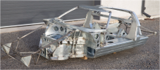
See Pic 4 Photo of original mild steel mono chassis
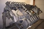
See Pic 4A showing the sill stiffening ribs (outer steel cover removed)
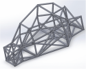
See Pic 5 Triangulated spaceframe chassis
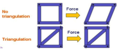
See Pic 6 The effect of triangulation
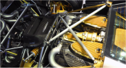
In a space frame chassis, in order to maximize stiffness, the tubes should be arranged so that the tubes are short and straight, are connected in triangles and are not asked to take bending loads. Where the chassis has to have openings for human access or for engine fitment, this area surround should be made as rigid as possible or have a triangulated frame, which bolts in to fill the gap as in the Pagani Zonda photograph. Some years ago, I used threaded steel bobbins welded into the frame at the junction of the tubes so that a stiffening frame could be bolted in to complete the structure.
See Pic 7 Pagani Zonda engine bay stiffening X frame
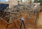
The idea of many small triangulated tubes was taken to the extreme in the Maserati Tipo 61“birdcage” chassis.
See Pic 8 Maserati Tip61 “birdcage chassis
Steel frame replica GT40s
Most of the steel frame replica GT40s suffer from several issues which significantly reduce stiffness.
There is usually very little or no triangulation. A rectangular shape is easily twisted and will easily deform into a lozenge shape. The panelling helps but the basic design needs improvement. Boxing in the sills as on the original cars would help a great deal as would a box beam running across the car at the seats line. With the sills boxed in, the tanks would need to be slid in from the end. The ribs in the sills would not need to be as big as the original items so that the normal type of fuel tank could be slid in and still retain a reasonable capacity for road use. In steel frame replicas the sills are essentially just angles made from square section tubes. This makes it easy to hang the fuel tanks but an angle is very weak compared to a tube or box section. Additionally, the roof/spider on most replicas is fiberglass rather than two steel pressings welded together and is relatively weak and so adds little to the overall stiffness of the chassis. A roll cage will help but there are safety issues if the driver is not wearing a helmet. The contribution the chassis stiffness of a roll cage is also hampered by the large door cut outs, the curved shape of the A pillars and the relatively small section in the middle joining the front to the bulkhead.
It is interesting to compare the stiffness of the same chassis with and without a roof. As can be seen in the list, the Bugatti chassis drops from 44,000 to 16,000 when it loses the roof. As most steel frame replicas have such a weak fiberglass roof section, they are in essence a convertible, so the main lower structure has to provide the stiffness.
As an aside, the usual material for steel frame chassis is square or rectangular ERW (electric resistance welded) tube, which is made from flat sheet folded and welded. It is flat on the outside but you can see the weld seam on the inside. It is cheap, easily available and easy to weld. Most race car space frames use CDS (cold drawn seamless) round tube or, more usually, round chrome/moly tube which is much stronger and lighter. The downside is not just the cost but round tube is very inconvenient when welding or attaching parts. Attaching body panels is also difficult whereas flat sided tube makes this straightforward.
There are other different monocoque designs, but many are not constructed from completely closed boxes or have flat sheet panels. If the chassis are “bathtub” designs then the benefits of the box structure are not evidenced. This is why the aluminium honeycomb chassis is so good as each panel is a box made up of many tiny boxes which makes it very light and very stiff. However the panels are flat sided and joining panels and attaching pick up points has to be done carefully so the loads are transferred correctly. Aluminium honeycomb is quite expensive and the panels are thick which reduces the available space. The later J cars made good use of this technology. Modern adhesives have made joining aluminium and honeycomb panels much easier but that is a subject for another day.
I hope you find it interesting,
Cheers
Mike
Chassis torsional stiffness
I am not a structural engineer but here is my amateurs attempt to understand chassis rigidity, especially the GT40 chassis in it’s many variations.
There are two main types of chassis – monocoque and spaceframe. Monocoques are boxes made from sheet material. Spaceframes are lattices made from steel tubes.
The idea of a chassis is to be a rigid structure to which various components can be attached – mainly suspension, engine and transmission. In order for the suspension to operate correctly, the chassis should be as rigid as possible so that when the car hits a bump or dip, the suspension moves rather than the chassis flexing.
Chassis torsional stiffness can be measured by bolting the front suspension pick up points to a solid concrete floor and placing a pivot at the centre of the rear of the chassis between the rear suspension pickup points. A long bar attached to the rear pick up points can then be loaded with heavy weights at a known distance from the pivot. This will twist the chassis. The twisting or torsional load can be calculated by multiplying the distance of the weight from the pivot by the size of the weight. The angle through which the chassis is twisted can be measured using a dial gauge to measure the deflection or more accurately by attaching a laser pointer aimed at a white board at a known distance. The angle can be calculated from the distance moved divided by the distance from the pivot of the measuring device. This number is the sine of the angle that the chassis has been twisted. The chassis stiffness is usually quoted in lbs.ft per degree (pounds times feet per degree) or N.m per degree (Newtons times metres per degree). So, if you have a strong concrete garage floor, a cheap laser pointer, a few resin anchors, some lengths of rigid steel and some known heavy weights then you can test your chassis, make changes and then retest to improve stiffness.
Below is a list of chassis and their torsional stiffness figures. I cannot vouch for their accuracy as they were collected from various sources on the internet. However, they are a reasonable indicator and give some interesting comparisons. Most steel frame GT40 replicas will be in the same range as the GTD Lola T70 replica and the Ultima.
**List of chassis and their stiffness in later post ( file to big for one post!
So, what makes a chassis torsionally stiff?
Answer. What it is made from and how that material is arranged.
Flat plate has almost zero stiffness but if bends and folds are put into it then it gets stiffer. Angle is a step forward and channel even better but still not good enough. If the sheet steel is made into box sections or round tube then it is very much improved.
See Pic. 1 Section stiffness
Obviously, whilst the solid section is rigid the weight rules it out for car purposes unless you have a need for a 3 ton GT40.
A monocoque chassis is made from sheet steel boxes. A spaceframe chassis is made from box or round tube joined up into a lattice.
See Pic 2 Monocoque compared to spaceframe
The original GT40 chassis and most modern cars are made from pressed sheet steel panels which are spot welded together to make boxes. These boxes are then attached to other boxes to make up the chassis. The boxes are often unusual shapes to fit occupants, doors or other items. It is easy to make a strong chassis from huge chunks of steel but a car chassis also needs to be as light as possible so the design of the chassis needs to provide the maximum stiffness for the minimum weight.
The original GT40 chassis were made from sheet mild steel pressings, which were mostly spot welded together into complex box sections. The roof or spider was a problem as it has big cutouts for the doors, which reduce the amount of stiffness contributed by the roof section. The lower chassis gets a lot of its stiffness from the sills, which are long boxes with internal stiffening ribs. These ribs made fuel tank fitting difficult, so in order to get the maximum volume of fuel, the bag tanks were made like a concertina to fit between the ribs. This made them a real toil to fit. It was obviously worth the hassle with the tanks to get the chassis stiffness. Other devices used to improve stiffness were the box section joining the sills across the car used for the seats. This cross beam is also used on the CAV stainless steel mono and the early minis. A central tunnel then forms a cross, and links the front and rear sections.
See Pic 3 Drawing of original mono chassis
See Pic 4 Photo of original mild steel mono chassis
See Pic 4A showing the sill stiffening ribs (outer steel cover removed)
See Pic 5 Triangulated spaceframe chassis
See Pic 6 The effect of triangulation
In a space frame chassis, in order to maximize stiffness, the tubes should be arranged so that the tubes are short and straight, are connected in triangles and are not asked to take bending loads. Where the chassis has to have openings for human access or for engine fitment, this area surround should be made as rigid as possible or have a triangulated frame, which bolts in to fill the gap as in the Pagani Zonda photograph. Some years ago, I used threaded steel bobbins welded into the frame at the junction of the tubes so that a stiffening frame could be bolted in to complete the structure.
See Pic 7 Pagani Zonda engine bay stiffening X frame
The idea of many small triangulated tubes was taken to the extreme in the Maserati Tipo 61“birdcage” chassis.
See Pic 8 Maserati Tip61 “birdcage chassis
Steel frame replica GT40s
Most of the steel frame replica GT40s suffer from several issues which significantly reduce stiffness.
There is usually very little or no triangulation. A rectangular shape is easily twisted and will easily deform into a lozenge shape. The panelling helps but the basic design needs improvement. Boxing in the sills as on the original cars would help a great deal as would a box beam running across the car at the seats line. With the sills boxed in, the tanks would need to be slid in from the end. The ribs in the sills would not need to be as big as the original items so that the normal type of fuel tank could be slid in and still retain a reasonable capacity for road use. In steel frame replicas the sills are essentially just angles made from square section tubes. This makes it easy to hang the fuel tanks but an angle is very weak compared to a tube or box section. Additionally, the roof/spider on most replicas is fiberglass rather than two steel pressings welded together and is relatively weak and so adds little to the overall stiffness of the chassis. A roll cage will help but there are safety issues if the driver is not wearing a helmet. The contribution the chassis stiffness of a roll cage is also hampered by the large door cut outs, the curved shape of the A pillars and the relatively small section in the middle joining the front to the bulkhead.
It is interesting to compare the stiffness of the same chassis with and without a roof. As can be seen in the list, the Bugatti chassis drops from 44,000 to 16,000 when it loses the roof. As most steel frame replicas have such a weak fiberglass roof section, they are in essence a convertible, so the main lower structure has to provide the stiffness.
As an aside, the usual material for steel frame chassis is square or rectangular ERW (electric resistance welded) tube, which is made from flat sheet folded and welded. It is flat on the outside but you can see the weld seam on the inside. It is cheap, easily available and easy to weld. Most race car space frames use CDS (cold drawn seamless) round tube or, more usually, round chrome/moly tube which is much stronger and lighter. The downside is not just the cost but round tube is very inconvenient when welding or attaching parts. Attaching body panels is also difficult whereas flat sided tube makes this straightforward.
There are other different monocoque designs, but many are not constructed from completely closed boxes or have flat sheet panels. If the chassis are “bathtub” designs then the benefits of the box structure are not evidenced. This is why the aluminium honeycomb chassis is so good as each panel is a box made up of many tiny boxes which makes it very light and very stiff. However the panels are flat sided and joining panels and attaching pick up points has to be done carefully so the loads are transferred correctly. Aluminium honeycomb is quite expensive and the panels are thick which reduces the available space. The later J cars made good use of this technology. Modern adhesives have made joining aluminium and honeycomb panels much easier but that is a subject for another day.
I hope you find it interesting,
Cheers
Mike
Last edited: