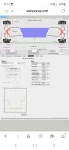
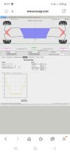
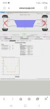
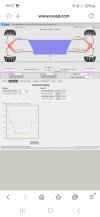
Hi all, hope all is well and everyone had a good Chritsmas. What is the desired front camber. Busy with my own home build frame, so using Vsusp calculator. Based on the mounting points I marked for myself I get to this

You are using an out of date browser. It may not display this or other websites correctly.
You should upgrade or use an alternative browser.
You should upgrade or use an alternative browser.
Camber front
- Thread starter CJ85
- Start date
Howard Jones
Supporter
What car, and used how? I think you will need to invest in a lengthy post concerning your vision to get any meaningful response.
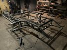
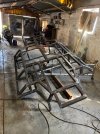
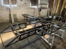
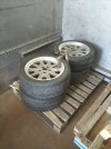
Hi Howard, Im in South Africa the GT40 kit that we had was the old KCC kit. Based on Ford Granada front and back. That being said and as in the intro I wanted to change to whole setup to indapendant front and rear. So new frame was build. Frame was build from Renes drawings, drawing it up in CAD again and then made a sts file for the CNC and cut it on a sheet of plywood. The car will be for road use so no extreams track driving. Motor wise I have Gen 3 Coyote with audi 5 speed. Plan is to make own uprights at the back using audi bearing and hub, front also looking at the ally upright that needs to be shorten. Im also looking at the e36 kingpin as a possibility for front. Wheels will be 17". The photos attached was when it was moved from where it was build back to my place, and finishing all the grinding on all the welds
Attachments
Howard Jones
Supporter
That chassis looks well designed. Well done. When you get done I would recommend you plot the camber, toe, and bumpstop change so you know what you have.
I would also recommend a baseline setup as follows.
F caster = 6 degrees (5-7) but equal on both sides
F camber = .25-.33 degrees neg.
F toe = 1/16 to 3/32 in each side
R toe = as close to straight ahead (0) as possible factoring in full suspension movement. no more than 1/16 inch inboard in addition to the necessary amount to achieve NO TOE OUT NO MATTER WHAT.
R camber = 0 -.25 degrees neg
This is a good street tire setup that will preserve your tires. A lot of camber, more than a .5 degrees negative, on the street, will really wear out your tires. I have run as much as 1-degree neg camber on my GT40. It did work better on the track but it severely ate the tires on the street. I would guess that much camber would reduce tire life by as much as 50%.
Hi Howard, thank you based on what you said and the screen shots on 1st post I still need to tweak the camber abit more upfront. Need to mock up the upper and lower control arms, just used the calculator to make sure the bolting points will be fine. Still need to go sit infront of car and see what the next step will be to get steering rack in a almost straight line so that the rack ends is not hanging down at an angle.
What you are doing now is the definition of making compromises.
Your camber is depending on how much body roll, jacking, rollbar (if you plan to run one), spring rates, tire width+wall heigh, what surface you drive on etc. If you have very little bodyroll during cornering you wont need that much camber as the contact surface will not be that much affected, given you not run narrow tall wall tires. Again if you have no roll you want transfer forces to the outer tire which again will cause less grip. This is a tradeoff in many ways...
Regarding steeringrack placement as a start; Keep the inner tierod pivot points on the same plane as your suspension arm pivot points. Make the steeringrod paralell to the lower suspension arm. It is advicable to arrange the steeringrack mounting so it is possible to shim or move it a bit when you start testing the car. Dont get too tied up in ackerman if that has crossed your mind yet...
Good to see the progress Christo
With regard to making rear uprights using Audi hubs you can see what I did in this post
https://www.gt40s.com/threads/canamsa-sa-stratch-build.19604/post-452747
Its post number 494
It was a real pain to get the bearing fit right, if I did it again I would start with a bolt on hub assembly from a production car
Hi Ole, I think I am abit caught in between Ackerman. Been reading and looking at diagrams, Im starting to make it more of a challange than what it is supposed to be maybe. The same with the Vsusp calculator. Trying to get everything to the T
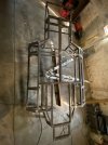
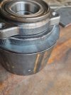
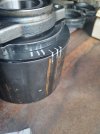
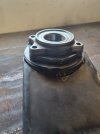
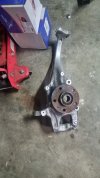
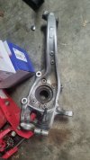
Fred wrt to rear uprights I have an idea and started with a mock up. Got hold of a 110mm dia pipe thats about 5mm thick. I then had a 5mm plate lazer cut, with the diameter of the bearing in the plate. Then took 10mm plate and had thatalso lazer cut in the shape of the bearing. All will be welded together and then the bearing will be a consumable with 4x bolts, thats included when you buy new bearings. The front part is the one in queation, I whant to use the ally upright knuckle from an audi. So would need to make it shorter and then come up with a plan to use or replace the bottom ball joint, just didnt get that far yet.
Fred wrt to rear uprights I have an idea and started with a mock up. Got hold of a 110mm dia pipe thats about 5mm thick. I then had a 5mm plate lazer cut, with the diameter of the bearing in the plate. Then took 10mm plate and had thatalso lazer cut in the shape of the bearing. All will be welded together and then the bearing will be a consumable with 4x bolts, thats included when you buy new bearings. The front part is the one in queation, I whant to use the ally upright knuckle from an audi. So would need to make it shorter and then come up with a plan to use or replace the bottom ball joint, just didnt get that far yet.
Attachments

Howard Jones
Supporter
It might be helpful to design in a range of adjustments instead of what the best guess might be as a final setting. As far as camber goes, you won't want it to go pos but might want to add neg. camber at some point. So I think if you can adjust from 0 to about -3 degrees you will be fine, especially with a predominantly street setup that you might like to take to the track in the future.
A good range for F caster would be from about 4 to about 7 or 8.
As far as Ackerman, antidive, and bump steer go I would try to adjust out any bump steer present at both front and rear and do my best to understand Ackerman etc. enough to compare to known good handling cars like a Challenge series Ferrari or a GT3 Porsche.
Ole is correct. You will find yourself making compromises. lots of compromises. A couple of things. First the longer the lower A-arms are the better off you will be, designing in as vertical a shock placement as possible, and again do your best to design out any bump steer as well as a low placement of the powertrain as possible and straight, 90 degrees to the centerline, alinement of the driveshafts.
Also. I would make the a-arm and shock mounting hardware simple to remove once the car is complete. Digging into the paneling to get to the through bolts so you can remove the lower a-arms is a pain in the ass. An example of difficult to work on would be the original lower front GTD and the upper F shock mount on an SLC.
Last edited:
Neil
Supporter
In a race car, Ackerman is largely academic. The tires are running at fairly large slip angles which defeats the whole purpose of Ackerman. On a street car it matters.It might be helpful to design in a range of adjustments instead of what the best guess might be as a final setting. As far as camber goes, you won't want it to go pos but might want to add neg. camber at some point. So I think if you can adjust from 0 to about -3 degrees you will be fine, especially with a predominantly street setup that you might like to take to the track in the future.
A good range for F caster would be from about 4 to about 7 or 8.
As far as Ackerman, antidive, and bump steer go I would try to adjust out any bump steer present at both front and rear and do my best to understand Ackerman etc. enough to compare to known good handling cars like a Challenge series Ferrari or a GT3 Porsche.
Ole is correct. You will find yourself making compromises. lots of compromises. A couple of things. First the longer the lower A-arms are the better off you will be, designing in as vertical a shock placement as possible, and again do your best to design out any bump steer as well as a low placement of the powertrain as possible and straight, 90 degrees to the centerline, alinement of the driveshafts.
Also. I would make the a-arm and shock mounting hardware simple to remove once the car is complete. Digging into the paneling to get to the through bolts so you can remove the lower a-arms is a pain in the ass. An example of difficult to work on would be the original lower front GTD and the upper shock mount on an SLC.
Similar threads
- Replies
- 9
- Views
- 504
- Replies
- 6
- Views
- 1K
- Replies
- 0
- Views
- 330