Hi Jerry, beautifull build I have to change the rod end on my gtd40,what is your size of the rose joint ont the front wishbones and on the rear ?thanks

Jerry, looking at your seat tracks & seat mounts (look familiar ), if the seat position still isn’t quite perfect you might consider elevating the front mount slightly higher. I found that gave me more headroom, more thigh support, and a more comfortable incline for pedal actuation.Been busy doing some house renovations and decorations so not a lot to report...
Finnished floor and fitted the pedal box proper
sorted out the throttle cable connection to the pedal
fittted the wiper motor
added a drop down mount for the seats and runners.
I did not want to drop the floor as wanted to keep a clean underside
I have angled the drivers seat a small amount to the center as that seemed to give me a more comfortable position with feet on pedals.
have done a dummy fit of the rear clip to align with the spider.
next job is to try and make all body panels align as best as i can before cutting and filling to bring all up to same level...
will temp fit front screen and screen that covers engine.
Pictures attached..
Thanks for looking and hope of use to other builders out there.
Jerry
Keep up the good work and keep posting.
Devin
will have a look later today ..Hi Jerry, beautifull build I have to change the rod end on my gtd40,what is your size of the rose joint ont the front wishbones and on the rear ?thanks
Jerry
Thanks Devin...Jerry, looking at your seat tracks & seat mounts (look familiar ), if the seat position still isn’t quite perfect you might consider elevating the front mount slightly higher. I found that gave me more headroom, more thigh support, and a more comfortable incline for pedal actuation.
Keep up the good work and keep posting.
Devin
Looks like a good plan.
will investigate when all sanding done and can re fit seats...
Jerry
not sure if this will help as dont know if gtd uses same wishbones / layout as my AK . Southern set up..Hi Jerry, beautifull build I have to change the rod end on my gtd40,what is your size of the rose joint ont the front wishbones and on the rear ?thanks
but here goes..
front wishbones top and bottom use 1/2 bore / thread for mounting to chassis
outer joint for wishbone to upright use a pressed in taper joint... no idea on part number / size ..
rear bottom wishbone locates to chassis by 1/2 bore / thread
outer joints pick up on 5/8 rod and use 5/8 bore / thread joints
top arm connects to upright with 5/8 bore / thread
inboard top arm connects to chassis with 1/2 bore / thread.
forward facing arms are 1/2 bore / thread both ends for both upper and lower.
Jerry
HI ALL...
I havent posted in a while as been busy sanding body panels...yawn..!!! so here are some updates....
Fitted the clam catches
had to do some fiberglassing of door edges as panel gaps were too large..
some pictures attached...
used the bevel edge method and built up the thickness
I havent posted in a while as been busy sanding body panels...yawn..!!! so here are some updates....
Fitted the clam catches
had to do some fiberglassing of door edges as panel gaps were too large..
some pictures attached...
used the bevel edge method and built up the thickness
Attachments
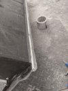
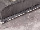
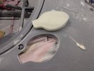
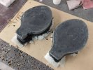
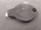
The latest part i have been working on is a cover for the fuel fillers.
Everyone has a different view on life and for me I dont like the fuel fillers sticking up above the bodywork, also they are bloody expensive !
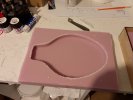
So i have opted for fillers that sit below the bodywork and to make a removable body contoured cover..
I started by making a foam insert to use as a buck
Everyone has a different view on life and for me I dont like the fuel fillers sticking up above the bodywork, also they are bloody expensive !
So i have opted for fillers that sit below the bodywork and to make a removable body contoured cover..
I started by making a foam insert to use as a buck
Attachments
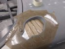
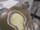
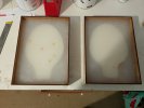
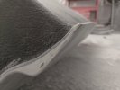
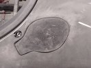
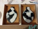
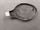
from the mould i made another buck but in fiberglass
These were then filled and shaped to be a nice fit and finnish into the front clip.
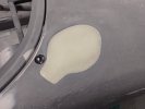
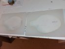
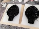
From these I then made a second mould from which to make the actual covers.
I have fitted them using the push poppers from Car builder solutions.
These were then filled and shaped to be a nice fit and finnish into the front clip.
From these I then made a second mould from which to make the actual covers.
I have fitted them using the push poppers from Car builder solutions.
Attachments
-
 IMG_20250322_112111.jpg367.3 KB · Views: 29
 -
 IMG_20250322_124135.jpg654.8 KB · Views: 32
 -
 IMG_20250322_144425.jpg531.3 KB · Views: 33
 -
 IMG_20250327_153535.jpg354.7 KB · Views: 35
 -
 IMG_20250328_093753.jpg211.2 KB · Views: 33
 -
 IMG_20250404_124447.jpg293.7 KB · Views: 40
 -
 IMG_20250404_124453.jpg404.3 KB · Views: 47
Back to some mechanical work now...
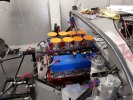
For a reason i dont know the engine sits very close to the bulkhead and the trumpets are nearly touching the rear glass,
I am going to have to take a sliver off the trumpet for clearance.
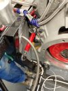
As the the whole power plant is sat on rubbers there will be some forward movement of the engine under braking.
I am sure this will cause some form of contact with the chassis.
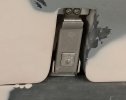
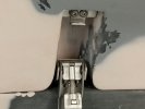
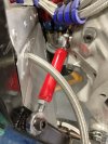
To overcome this I have added a brace longitudily between the engine and chassis.
I was able to pick up on a 1/2 UNC thread already on the engine and just had to weld in a 1/2 unf boss to locate a couple of rod ends.
This will still allow the engine to move about on its rubbers but will stop forward movement..
Pictures attached below.
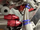
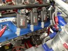
also had too tight a fit for the coil on plug coils against the water pipes to the swirl pot.
These mount on a frame that then sits on a couple of pedastals.
I have cut this frame about and bolted straight to the rocker covers which allowed me to move it towards the rear and make clearance for the water pipes.
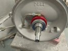
the next task was sorting out the clutch operation...
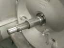
AK Sports cars ( Jon) came to my rescue here....
They supplied a new machined cover that replaces the QUAIFFE cover over the input shaft.
This allows a GM centre thrust to slide over.
This is the kit that they use for thier Coyote engine install.
The only change I had to do was to remove another 2.5 mm from the step to allow the thrust to sit closer to the box.
For a reason i dont know the engine sits very close to the bulkhead and the trumpets are nearly touching the rear glass,
I am going to have to take a sliver off the trumpet for clearance.
As the the whole power plant is sat on rubbers there will be some forward movement of the engine under braking.
I am sure this will cause some form of contact with the chassis.
To overcome this I have added a brace longitudily between the engine and chassis.
I was able to pick up on a 1/2 UNC thread already on the engine and just had to weld in a 1/2 unf boss to locate a couple of rod ends.
This will still allow the engine to move about on its rubbers but will stop forward movement..
Pictures attached below.
also had too tight a fit for the coil on plug coils against the water pipes to the swirl pot.
These mount on a frame that then sits on a couple of pedastals.
I have cut this frame about and bolted straight to the rocker covers which allowed me to move it towards the rear and make clearance for the water pipes.
the next task was sorting out the clutch operation...
AK Sports cars ( Jon) came to my rescue here....
They supplied a new machined cover that replaces the QUAIFFE cover over the input shaft.
This allows a GM centre thrust to slide over.
This is the kit that they use for thier Coyote engine install.
The only change I had to do was to remove another 2.5 mm from the step to allow the thrust to sit closer to the box.
Attachments
-
 brace 1.jpg283.9 KB · Views: 39
 -
 brace 2.jpg361.5 KB · Views: 38
 -
 brace with left and right hand rose joints.jpg227.9 KB · Views: 47
 -
 engine close to bulkhead.jpg429.8 KB · Views: 46
 -
 IMG_20250415_102404.jpg506.6 KB · Views: 47
 -
 new input cover machined to accept GM Center thrust bearing..jpg251.2 KB · Views: 39
 -
 gm centre thrust fitted.jpg326.5 KB · Views: 47
Similar threads
- Replies
- 19
- Views
- 5K