
You are using an out of date browser. It may not display this or other websites correctly.
You should upgrade or use an alternative browser.
You should upgrade or use an alternative browser.
David's Monocoque Build
- Thread starter David Deschamps
- Start date
David,
When you get these parts formed up, what are you doing with them?
Do you give them a coat of 1k etch/weld through primer and then put them in storage? are they going in a closed container with a bunch of desiccant to protect the parts from rust whilst you get more parts formed up?
I feel I should also start doing some of what you are doing. At present I have just been working on collecting and restoring the bolt on parts whilst I finish my CAD work. Trying to plan ahead.
Keep up the good work.
Ryan
I wipe them down with WD40 and store them in a heated room, any surface rust I treat with Evapo-Rust and a Scotchbrite pad.David,
When you get these parts formed up, what are you doing with them?
Do you give them a coat of 1k etch/weld through primer and then put them in storage? are they going in a closed container with a bunch of desiccant to protect the parts from rust whilst you get more parts formed up?
I feel I should also start doing some of what you are doing. At present I have just been working on collecting and restoring the bolt on parts whilst I finish my CAD work. Trying to plan ahead.
Keep up the good work.
Ryan
Yes, the hammer form.Is that to hammer form the blank over?
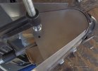
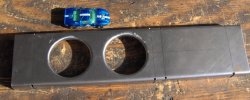
2443 rear window frame. With the 20ga steel blank clamped and pined it's time to start tapping the steel over the form. IM000011 is the first pass. IM000014 tucks develop and the low tuck must be pulled out and more tapping to get IM000018.
Attachments

2443 Cont. Put the blank back on the form after trim to get the corners in more. Very light tapping on the dolly to get the corners in even more, tap to hard and the metal will stretch in a area you want to shrink.
Attachments
Last edited:
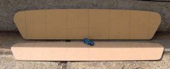
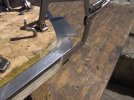
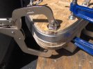
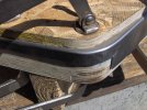
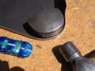
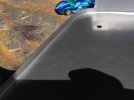
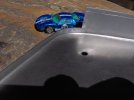
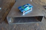
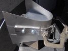
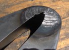
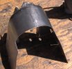
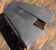
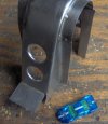
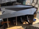
This panel is not part of my build I made it just for fun. X40-60
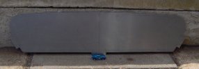
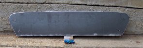
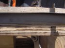
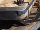
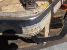
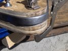
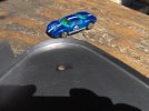
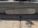
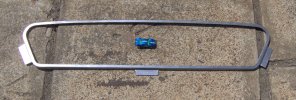
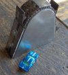
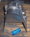
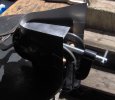
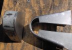
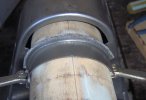
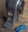
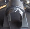
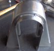
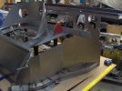
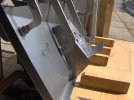
First photo is X40-60 from car 103. Second to fourth photo is the steel hammer form, I knew it was a long shot that the steel would shrink enough to lay flat. I managed to shrink the steel quite a bit but the steel has been over worked and cracks are starting to appear. Second method is cutting down the shrink area and welding in the flange.
First photo is X40-60 from car 103. Second to fourth photo is the steel hammer form, I knew it was a long shot that the steel would shrink enough to lay flat. I managed to shrink the steel quite a bit but the steel has been over worked and cracks are starting to appear. Second method is cutting down the shrink area and welding in the flange.
Attachments
-
 Screenshot (3475).png870.1 KB · Views: 183
 -
 Hammer-Form1.JPG597.7 KB · Views: 172
 -
 HammerForm2.JPG436.6 KB · Views: 169
 -
 HammerForm3.JPG298.7 KB · Views: 170
 -
 HFB4.JPG254.5 KB · Views: 166
 -
 HFB5.JPG313 KB · Views: 162
 -
 HFB6.JPG509.7 KB · Views: 160
 -
 HFB7.JPG584.2 KB · Views: 159
 -
 HFB8.JPG388 KB · Views: 166
 -
 HFB9.JPG326.2 KB · Views: 173
fabulous work David. It really gives some insight into the skill and fabrication knowledge that was around at that time. A similar profile is also use at the inner edge of the door pillar as it cascades down the inside edge of the side sill.
I wonder if you would have better luck hammer forming both turns at the onetime rather than trying to come back and add the second return after the first has already been folded?
Ryan
I wonder if you would have better luck hammer forming both turns at the onetime rather than trying to come back and add the second return after the first has already been folded?
Ryan
The panel at the door pillar base 2014-5 is hard to make without stamping it, at least in one single piece of steel. So far I have not seen a single piece and no welding for 2014-5, so I don't feel bad about how I made mine (more on that later).
I think the second return could get sloppy if both were done at the same time but more experimenting will be necessary.
If I was to do it again I would make a MDF hammer form and weld in the flange, the second side was stuck on the form so I know it took the shape. Much less force was needed for the second side so MDF would be OK.
fabulous work David. It really gives some insight into the skill and fabrication knowledge that was around at that time. A similar profile is also use at the inner edge of the door pillar as it cascades down the inside edge of the side sill.
I wonder if you would have better luck hammer forming both turns at the onetime rather than trying to come back and add the second return after the first has already been folded?
Ryan
very nice build, will keep watching your progress
jim
jim
Randy Folsom
Supporter
I don’t think you will be troubled by trolls on this forum. The admins are really good about making sure this site is a great resource for all.I'll be building a monocoque using as many FAV drawings as possible and when not available I will make parts of my own design. So as long as this build log stays friendly I will continue to update it.

Similar threads
- Replies
- 15
- Views
- 2K
- Replies
- 14
- Views
- 2K