
thank you, I guess the only option I have at this point is to oversize the holes a bit and then cross my fingers , Cam has not had any problems with the windows cracking so far, he did the counter -sink bolts and rubber nutsFWIW, the directions from Shields (who is/was the manufacturer of the parts) says not to counter-sink the holes .... I've always thought the trick to avoiding cracks in the plastic is a slightly over-sized hole and then cushion the bolt head with a rubber washer .... that's how I did my windshield using 4 #6s and it's been fine for 15 years. YMMV.

You are using an out of date browser. It may not display this or other websites correctly.
You should upgrade or use an alternative browser.
You should upgrade or use an alternative browser.
Restarting my SLC project in West Texas
- Thread starter felizguy
- Start date
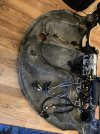
Well, always trying to get things done , cleaned up all the wiring behind dashboard. everything is connected by Delphi weathercock connectors, including speakers, power to stereo and amp, backup camera and so on. Taking the dashboard on and off should be straight forward with just two bolts.
Attachments
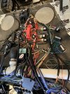
While I was in wiring mode also cleaned up, labeled and created wiring diagram for all the wires on top of the footboy. Per Howard's suggestion I brought a HUGE ground wire that is grounded both to the chassis and engine, as well as a power wire , and created a negative and and a positive power bank. , relays for the fans , brake line switch , as well as controllers for the full sender and the Tesla parking brake.
Attachments
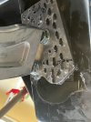
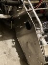
Well, as I was on the to of the footboy, I also finished securing the Frankenstein tow hook support Frame I made it with spare Graziano transmission brackets I had , anchored all the way through the middle beam that runs through the footboy. As well as a couple of additional bolts, just because. Not pretty, but effective.
Attachments
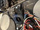
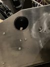
Next was connecting 2 wheel sensors, one for the traction control unit and the other for the AIM unit , I probably could have integrated both circuits with one sensor, (but I don't have my son Miguel, who is now at MIT) to help me I wanted to have a mechanical signal for the speedometer , I can always add a GPS signal as well. But I am a mechanical guy, what can I say. holes were drill on the back of the rotor in an area that should not compromise strength to meet the depth and with requirements for the sensors at high rpm speeds.
Lastly, needed to bring the wires to the top of the footbox in order to connect to the AIM Strada digital dash unit and the traction control controller on the dashboard.
Lastly, needed to bring the wires to the top of the footbox in order to connect to the AIM Strada digital dash unit and the traction control controller on the dashboard.
Attachments
It sure looks easy when you look at the pictures, LOL. This took a while
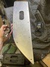
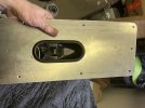
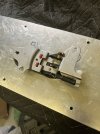
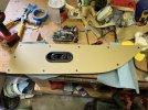
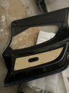
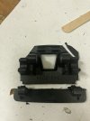
1. Created a close out panel that will accommodate the door opening mechanism
2. Figured out where to install the mechanism
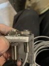
3. Choose to bolt to the panel using aluminum spacers. I did not trust epoxying alone so I added counter bore screes to attach the cylinder spacers to the panel. The mechanism is then bolted directly to the threaded spacers.
4. Finally wrapped it in leather.
Easy , right ??? Of course takes ten times longer that anticipated, all the fine tuning, grinding , measuring and so on. par for the course.
1. Created a close out panel that will accommodate the door opening mechanism
2. Figured out where to install the mechanism
3. Choose to bolt to the panel using aluminum spacers. I did not trust epoxying alone so I added counter bore screes to attach the cylinder spacers to the panel. The mechanism is then bolted directly to the threaded spacers.
4. Finally wrapped it in leather.
Easy , right ??? Of course takes ten times longer that anticipated, all the fine tuning, grinding , measuring and so on. par for the course.
Attachments
I wont spend much time on this doorlock modification, I copied it exactly from Cam's design here is the link to his awesome SLC build website https://socalslc.com/2019/09/18/72-sometimes-you-need-a-year-to-figure-things-out/.
Attachments
I have to admit that in my mind this was one of the coolest parts of the build , yes, hard to believe, but it is true.
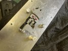
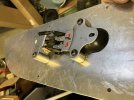
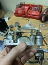
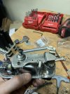
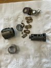
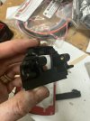
you can't buy a pair of door locks that will fit the same key, so you have to order 2 locks that accommodate 2 different keys, so get a locksmith? No , get on you tube and figure it out.
I ordered a cheap, junk lock to take it apart and figure things out, then modified one of the new ones I ordered to match the other .
The order of the pins determines the profile of the key.
So I Took apart the locking mechanism, and made both match the same key. Fascinating, the details on door lock design .
Now if I could remember where I placed the right set of keys. For real, I found the wrong set and can't find the right pair right now.
Attachments
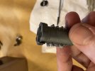
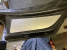
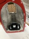
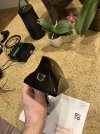
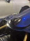
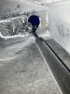
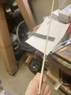
Next was the rear view mirror mod. I chose the gentex full display mirror, it came with a couple of mounting options, then I chose a generic FM antenna shark fin type plastic frame. the challenge was how to attach the mounting frame to the inside of the mirror, I cut the mounting Frame and mounted it with a strong plastic epoxy.
As it turns out everything was perfect except one slight oversight, the camera was upside down , therefore my mirror has to be upside down as well, by the time I realized everything it was too late to start over , so I will learn to live with an upside down mirror")
I cut the camera opening at the front and I covered with plexiglass to prevent water and critters form getting in.
I drilled 2 little holes on the sides to access the camera mounting screws, you can loosen them and adjust the camera up and down as needed to find the perfect position. (very hard to see the holes on the side view of the shark fin)
As it turns out everything was perfect except one slight oversight, the camera was upside down , therefore my mirror has to be upside down as well, by the time I realized everything it was too late to start over , so I will learn to live with an upside down mirror
I cut the camera opening at the front and I covered with plexiglass to prevent water and critters form getting in.
I drilled 2 little holes on the sides to access the camera mounting screws, you can loosen them and adjust the camera up and down as needed to find the perfect position. (very hard to see the holes on the side view of the shark fin)
Attachments
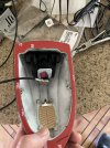
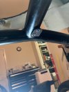
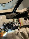
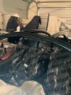
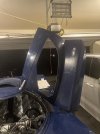
Next was to figure out the mirror location, I looked at a few cars to find the best ergonomic position, it turned out to be at the intersection of the front hoop and the passenger side bar that attaches between the front and rear hoops.
I used the metal mounting tab and attached it by drilling and tapping 2 mounting holes on the cage.
The pictures shown do not show the mirror being upside down, now it is ;-)
I used the metal mounting tab and attached it by drilling and tapping 2 mounting holes on the cage.
The pictures shown do not show the mirror being upside down, now it is ;-)
Attachments
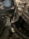
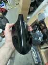
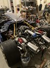
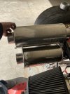
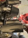
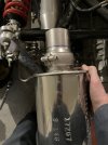
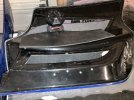
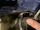
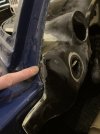
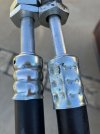
While messing around with the rear clam when installing the tail lights, I realized that the muffler I chose was sticking too far, especially since I had to make the opening smaller due to the size of the new tail lights I chose.
So I had to find a shorter set of mufflers, and since I did not want to repeat the cut, grind, reweld process again , I found very cool clamps that allow some movement in order to help with the final orientation that would fit through the new , much smaller openings on the rear clam .
I still needed to weld both ends of the new adjustable clamp to the muffler and to the catalytic converter on the other side.
Attachments
Door mounting:
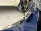
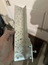
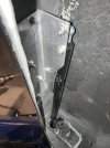
I decided to go with the struts inside the door allowing for a full 90 degree opening, same as Cam did. I forgot if this was an original Mesa modification, it was difficult to execute but works very well, the down side is the strut puts a constant tension on the door when the the door is closed, deforming it a little bit . It makes making constant gaps all around the door very difficult but not impossible.
Of note also os that new longer and stronger struts are needed. Mcmaster Carr has has an endless combination of lengths and strengths selection https://www.mcmaster.com/products/gas-struts/gas-springs-7/
fist was to locate the mounting bracket on the body, then a solid frame for the mounting bracket on the door that will be epoxied and bolted to the inside of the door .
A difficult part was to figure out the travel path of the strut on the door opening , not straight forward at all , created a super weird irregular moon shape. Go figure . Cam has a video from inside the which is really cool. https://socalslc.com/2018/04/07/31-roughing-the-body/
I also added two metal plates to sandwich the fiberglass at the bolting location of the hinges for extra support.
This was a slow painful process to say the least, but with excellent results.
One of the coolest times on the build was seeing the doors open and close.
Attachments
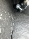
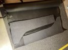
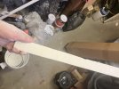
I added insulation to the inside of the doors, and also to the spider, second skin luxury liner pro has a product that combines mass loaded vinyl rubber with closed cell polyethylene foam , very expensive, I figured I could save some money by ordering generic components separately and making the sandwich myself, I do not recommend that route, is difficult and time consuming, just use the second skin luxury liner pro and save a TON of time.
furthermore, the rubber does not adhere to fiberglass very well but the polyethylene foam does,
Dap weldwood contact cement works best for everything, foam, rubber, leather, carpeting. Believe me I tried several other glues nothing is as good, just apply to both sides, dry with a heat gun for 1 1/2 minutes and then push and massage as hard as you can and voila, a super strong bond.
The last picture shows making the sandwich with the rubber being bonded to the foam, then the foam side is bonded to the fiberglass. Note that the other way does not work, the rubber does not bond well to the fiberglass.
Attachments
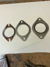
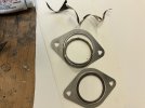
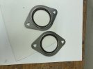
I forgot to post about my custom metal gasket between the exhaust manifold and the down tube, for some reason one of the gaskets available does not fit the bolt holes well and the other has a diameter that is a bit large, solution, create a hybrid one using both gaskets , now I have the right bolt hole opening and the right diameter for optimum sealing.
You may want to look at my post of the mystery burning catalytic converter due to the missing gaskets. That sucked!!
You may want to look at my post of the mystery burning catalytic converter due to the missing gaskets. That sucked!!
Attachments
A couple of mods done to the dashboard, I added some fiberglass to eliminate a gap between the dashboard and the body
I added a dimple on the fiberglass to accommodate the travel of the lever forward to activate the brights , even though I needed to add fiberglass to the other side to eliminate a hole, I figure it was easier then moving the entire steering column towards the driver a half inch .
I added a dimple on the fiberglass to accommodate the travel of the lever forward to activate the brights , even though I needed to add fiberglass to the other side to eliminate a hole, I figure it was easier then moving the entire steering column towards the driver a half inch .
Attachments
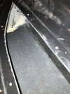
While doing the final fitting details, I had to add some wedges between the aluminum frame and the spider to create a nice gap between the front clam and the spider
Of note is that the wedges were thicker at the front, it took a lot of grinding and sending to get them perfect, then epoxied to the spider.
Of note is that the wedges were thicker at the front, it took a lot of grinding and sending to get them perfect, then epoxied to the spider.
Attachments

Chasing an A/C leak
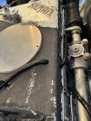
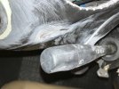
So I decided to go ahead and connect the a/c compressor and charge the unit , but before charging I checked if the system was able to hold vacuum and it was not . Howard suggested adding positive pressure , since the system was not charged ye, and I did , voila, the leak was very loud and easy to find, It was one of my crimps that was bad , only one !!
So I went to a local hydraulic shop and had the hose crimped professionally , since I do not own a crimping tool, I borrowed one the last time.
It sure looked pretty, so I connected everything , vacuum seemed to hold , then charged the system , and a massive leak on the newly professionally crimped hose, the only thing I can think of is that equipment is made for hydraulic hoses , it is probably a slightly different diameter than cooling hoses .
So finally ordered a professionally crimped hose with the right fittings and the right length, should do it this time .
Installed the hose, which was a major pain, now that the footbox is fully insulated. So note for future builders, troubleshoot your a/c hoses before you insulate your footbox.
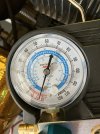
So connected everything and vacuum would not hold at all, applied positive pressure and no leaks found , even used the black light stuff and nothing , no leak found . over and over I tried, no leak . What's going on?
I finally decided to try a new manifold and voila, the harbor freight special had a leaky gauge, very frustrating, now vacuum held overnight and charged the system one more time. everything works great now.
Moral of the story , cheap stuff breaks after a couple of uses sometimes. You get what you pay for. And sometimes professionally done does not mean better if not using the proper equipment.
Looking back I did notice that the gauge was acting a bit erratic with the readings , but I did not think about a leak
So I decided to go ahead and connect the a/c compressor and charge the unit , but before charging I checked if the system was able to hold vacuum and it was not . Howard suggested adding positive pressure , since the system was not charged ye, and I did , voila, the leak was very loud and easy to find, It was one of my crimps that was bad , only one !!
So I went to a local hydraulic shop and had the hose crimped professionally , since I do not own a crimping tool, I borrowed one the last time.
It sure looked pretty, so I connected everything , vacuum seemed to hold , then charged the system , and a massive leak on the newly professionally crimped hose, the only thing I can think of is that equipment is made for hydraulic hoses , it is probably a slightly different diameter than cooling hoses .
So finally ordered a professionally crimped hose with the right fittings and the right length, should do it this time .
Installed the hose, which was a major pain, now that the footbox is fully insulated. So note for future builders, troubleshoot your a/c hoses before you insulate your footbox.
So connected everything and vacuum would not hold at all, applied positive pressure and no leaks found , even used the black light stuff and nothing , no leak found . over and over I tried, no leak . What's going on?
I finally decided to try a new manifold and voila, the harbor freight special had a leaky gauge, very frustrating, now vacuum held overnight and charged the system one more time. everything works great now.
Moral of the story , cheap stuff breaks after a couple of uses sometimes. You get what you pay for. And sometimes professionally done does not mean better if not using the proper equipment.
Looking back I did notice that the gauge was acting a bit erratic with the readings , but I did not think about a leak
Attachments
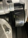
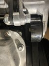
While installing the a/c compressor a weird thing happened
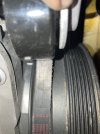
I used an aftermarket kit that provided better contact between the a/c pulley and the belt , but when I was attaching the belt I noticed that the tensioner rubbed against a bolt and the belt was riding on the edge of the tensioner, that did not look right
Sure enough the bearing was not properly press fit, I used a socket and push it all the way in with my bench vise.
A poorly manufactured and poorly inspected item, why doe that always happen to me? The list is long .
Attachments

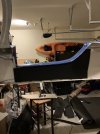
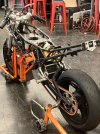
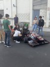
A couple of fun posts, this was the fall , I got to visit my son Miguel at MIT , and I did sit on a lecture, so I can say that I went to school at MIT . the place is awesome, some of the highlights, a night picture of the dome, a hydrogen powered motorcycle and my son is a member of the racing team, very cool . I also added my Mandalorian Halloween outfit, because being a pediatrician , I do stuff like that at work . Fun!!!
. the place is awesome, some of the highlights, a night picture of the dome, a hydrogen powered motorcycle and my son is a member of the racing team, very cool . I also added my Mandalorian Halloween outfit, because being a pediatrician , I do stuff like that at work . Fun!!!Attachments


Similar threads
- Replies
- 19
- Views
- 3K
- Replies
- 8
- Views
- 1K
- Replies
- 16
- Views
- 7K