
You are using an out of date browser. It may not display this or other websites correctly.
You should upgrade or use an alternative browser.
You should upgrade or use an alternative browser.
Steve's RCR GT40 Build
- Thread starter steveklafeta
- Start date

I have 4 an hard line from the top of the radiator to bleed into the overflow tank. I plan on taking another line from the top of the engine above the thermostat housing as well.


Is there a reason I can’t T them together at the tank? Or is it better to weld another bung into the tank?
Is there a reason I can’t T them together at the tank? Or is it better to weld another bung into the tank?
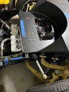
I also finished the steering.
There is very little room for the petals. I had to reverse the brake petal pad and cut the end off to get clearance. Even without the plates for the adjustable petals it’s close. I did cut the shelf and recessed the rose joint (I think that’s what it is called).
Attachments
My original plan with the dash and wiring was extremely short sighted. I, like many, didn’t have the steering rack. So, I went ahead and wired the dash directly. I left all of six inches of slack. Well you can imagine the nightmare when I had to disconnect everything to get the steering done.

I decided to rework the whole thing. I don’t know why I feared the connectors.


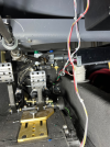
Kindly ignore the passenger seat. That’s the controller for the electric water pump with 5 miles of wire attached. Yet there is a tiny indicator light for the dash with 4 inches of wire. Makes no sense.

This is my accessory fuse panel. It’s tucked behind the air conditioning unit on the passenger side.
I decided to rework the whole thing. I don’t know why I feared the connectors.
Kindly ignore the passenger seat. That’s the controller for the electric water pump with 5 miles of wire attached. Yet there is a tiny indicator light for the dash with 4 inches of wire. Makes no sense.
This is my accessory fuse panel. It’s tucked behind the air conditioning unit on the passenger side.
Randy Folsom
Supporter
I am so grateful for your documentation. Thx much.
Neil
Supporter
Steve- I am not singling out your post, these are just some recommendations for wiring any home- built car. Frequently a project is finished with great attention to craftsmanship but its electrical wiring is a rat's nest.
Neat wiring isn't easy but it can be accomplished with some forethought. My suggestion is to use a connector if a panel or component may need to be removed. There are many types of connectors with a variety of pin choices. If it is necessary to put a connector on a low level signal such as a tach signal, ABS feedback, TPS, or gauges, A gold- plated pin is the best choice. Gold does not corrode or tarnish so electrical contact is maintained even while passing very low voltages and currents. Silver or tin- plated pins are fine for power connections but not for "dry circuits". Intermittent contacts can often be traced to connector pin problems.
Wiring layout is best accomplished by laying out a harness path to the electrical components on a sheet of paper and then adding actual wiring, following the drawn harness path. Allow extra length before cutting a wire to final length. After everything is in place the wire can be cut to required length and terminals crimped on. Needless to say, do NOT use the same color wire throughout! For the fastidious, lacing cord is one way of tying up the loose wiring into a good looking harness but small Ty-Wraps do just as well and are easy to install and remove.
Here is how I built and wired my switch panel. It does not use a connector since it is attached to the chassis by quick-release thumb screws and it

 tips down for easy access to the rear.
Neat wiring isn't easy but it can be accomplished with some forethought. My suggestion is to use a connector if a panel or component may need to be removed. There are many types of connectors with a variety of pin choices. If it is necessary to put a connector on a low level signal such as a tach signal, ABS feedback, TPS, or gauges, A gold- plated pin is the best choice. Gold does not corrode or tarnish so electrical contact is maintained even while passing very low voltages and currents. Silver or tin- plated pins are fine for power connections but not for "dry circuits". Intermittent contacts can often be traced to connector pin problems.
Wiring layout is best accomplished by laying out a harness path to the electrical components on a sheet of paper and then adding actual wiring, following the drawn harness path. Allow extra length before cutting a wire to final length. After everything is in place the wire can be cut to required length and terminals crimped on. Needless to say, do NOT use the same color wire throughout! For the fastidious, lacing cord is one way of tying up the loose wiring into a good looking harness but small Ty-Wraps do just as well and are easy to install and remove.
Here is how I built and wired my switch panel. It does not use a connector since it is attached to the chassis by quick-release thumb screws and it
I take your “rat’s nest” comment as a compliment. That description is a massive improvement from the abortion that existed before. I now have 7 plugs and the capillary tube to connect the dash. This experience was a fantastic blessing in disguise. I found that I connected a white ground wire from the trinary switch to the ground off the blower relay. The directions on wiring the vintage air system are on 2 different pages and the power blower relay is much different from the power fan relay. Nonetheless, I heard the vintage air blower fan go on for the first time. It brought a tear to my eye. So far so good. Everything I wired works and no fires.
Good luck with the CV joint boots (bellows, gaiters)!View attachment 144471
View attachment 144472View attachment 144473
I also finished the steering. View attachment 144475View attachment 144476
There is very little room for the petals. I had to reverse the brake petal pad and cut the end off to get clearance. Even without the plates for the adjustable petals it’s close. I did cut the shelf and recessed the rose joint (I think that’s what it is called). View attachment 144477
It appears you have significantly shortened the brake pedal lever arm length. I fear that you will then find the pedal effort unacceptably high. This may be able to be addressed by fitting smaller bore cylinders but then you may run into trouble with the pedal travel.
Attachments
I think I will be able to reverse the petal pad and still clear the steering rack. That will help with the height some. Its also tipped way forward in this picture.
Walter, you can’t just drop that cryptic message without context. I’m a delicate flower and too fragile at this point in the build. What problems do I need to anticipate with the boots?
Walter, you can’t just drop that cryptic message without context. I’m a delicate flower and too fragile at this point in the build. What problems do I need to anticipate with the boots?