
You are using an out of date browser. It may not display this or other websites correctly.
You should upgrade or use an alternative browser.
You should upgrade or use an alternative browser.
Scratch build MK IV
- Thread starter RexDanni
- Start date
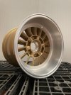
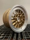
You don’t ever need to apologize for posting eye candy…Sorry to start this again, but they finally arrived today - I'm a bit proud of them
")
Davidmgbv8
Supporter
The quality, fit and finish appears superb! Who made them? I do have a question as to what the elongated slots are for and are they a size that is smaller than the pin drive so the pin cannot accidentally go into the slots?
The slotted holes have several functions.
Firstly, they are slightly smaller so that the bobbins only fit into the holes when mounting the wheels and not into the slotted holes. You have recognized this correctly.
Then, of course, to save weight.
The last task is to reduce the contact surface of the rim on the hub. By opening up the contact surface, the contact surface becomes "softer", i.e. the local stresses generated by heat are reduced, which is good against cracking at the holes in the bobbins and the hub.
This can be further improved by using cross-shaped slots.
But I did not do this.
As my tolerance in the area of the bobbins is +0.00/-0.03mm, this would be necessary to be able to carry out a quick wheel change when the car is hot and the new rim is cold.
But I don't need a wheel change under racing conditions.
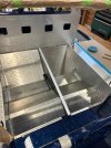
I am currently working on my tank system.
I have attached a few pictures of how the system is set up. Since my engine has a carburetor, I only work with a fuel pump directly in the tank. I have opted for the AEROMOTIVE Phantom 200 Stealth system.
Unfortunately, AEROMOTIVE does not have a drawing of the hole pattern. They sent me the dimensions by e-mail. I sent AEROMOTIVE a drawing of the hole pattern and a 3D drawing of the whole part back
If anyone here needs this, just let me know.
Last week I had the two tanks welded by a friend and today I carried out a leak test.
I also bought a safety valve that opens at 0.2 bar. These are used in heating systems in houses, are very cheap and accurate. Then lids to close the hand hole lids, without internal cut-outs. I fitted a rim valve in one lid and the safety valve in another.
It was not so easy to get the lid screws tight for the test. I used a copper washer and a Teflon washer in each case.
Then I carefully inflated the whole thing and checked all the weld seams with leak detection spray.
One tank is tight and the other still has a tiny hole in a weld seam, which we still have to rework.
Then I can finally install the tanks, then glue honeycomb sandwich panels to the inside of the side box cladding as a crash structure and the side boxes are finally finished.
If any of you need the CAD files (DXF and Step) to rebuild the tanks, just let me know and I'll send it to you.
Have a nice weekend
Hello everyone,
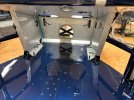
now I have found the first big mistake in my construction, I have been waiting for it...
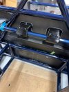
Unfortunately, I made the cross tube in my roll bar too high. I actually wanted to attach my seat belts to it.
But it looks like it's now too high. Even if I put the attachment on the underside of the tube.
What do you think?
I can't think of a good solution that doesn't involve welding.
The sheets on the front and rear of the roll bar are made of 1.5mm aluminum.
Nothing will hold on to them, also not when I connect them inside with a box.
Can you think of something that would work without an angle grinder and welding equipment?


now I have found the first big mistake in my construction, I have been waiting for it...
Unfortunately, I made the cross tube in my roll bar too high. I actually wanted to attach my seat belts to it.
But it looks like it's now too high. Even if I put the attachment on the underside of the tube.
What do you think?
I can't think of a good solution that doesn't involve welding.
The sheets on the front and rear of the roll bar are made of 1.5mm aluminum.
Nothing will hold on to them, also not when I connect them inside with a box.
Can you think of something that would work without an angle grinder and welding equipment?
Neil
Supporter
The present shoulder harness attachment points would not pass SCTA tech inspection. Is it possible to change the attachment point from the horizontal cross tube to the diagonal brace tubes below?Hello everyone,
now I have found the first big mistake in my construction, I have been waiting for it...
Unfortunately, I made the cross tube in my roll bar too high. I actually wanted to attach my seat belts to it.
But it looks like it's now too high. Even if I put the attachment on the underside of the tube.
What do you think?
I can't think of a good solution that doesn't involve welding.
The sheets on the front and rear of the roll bar are made of 1.5mm aluminum.
Nothing will hold on to them, also not when I connect them inside with a box.
Can you think of something that would work without an angle grinder and welding equipment?
View attachment 140224
View attachment 140225
View attachment 140226
In Germany, this would also not be permitted at motorsport events 
Unfortunately not, as the cross tube runs too far outwards.
According to the regulations, it should look like this:
The pictures show how it should ideally look (red circles)
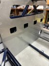
I also have a problem with the minimum distance of 90mm (last picture)
Hmm... the more I get into it, the more difficult it gets...
I should have done it before.


Unfortunately not, as the cross tube runs too far outwards.
According to the regulations, it should look like this:
The pictures show how it should ideally look (red circles)
I also have a problem with the minimum distance of 90mm (last picture)
Hmm... the more I get into it, the more difficult it gets...
I should have done it before.
Ian Anderson
Lifetime Supporter
Is your “man” in the right location?
it looks like his head is too far from the roof or slumped too far down in the seat.
If he sits back and upright the belts may be in the right position
Ian
it looks like his head is too far from the roof or slumped too far down in the seat.
If he sits back and upright the belts may be in the right position
Ian
My dummy is not quite perfect, but it is aligned the way I sit in the car.
The MK IV is even lower than an MK I or II.
Sitting upright is unfortunately not possible without coming into conflict with the center strut of the roll bar in the event of a side impact.
there's nothing wrong with the slightly more reclined position, it's just that attaching the shoulder straps is now difficult
PMHow it looks like?
Howard Jones
Supporter
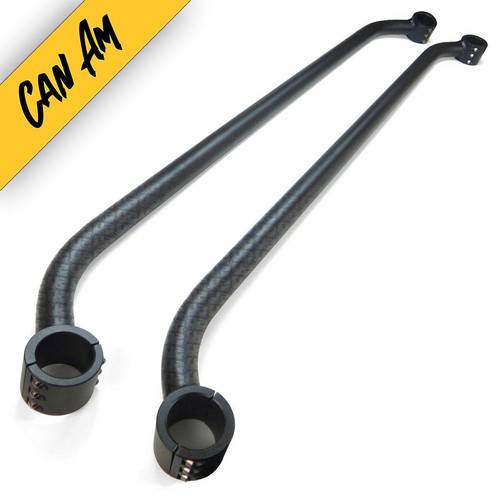
This won't work per se, but if you made something similar to this it could be bolted into your present roll cage. If it was bolted behind the rollbar then it will also get you a couple of inches of clearance to the seatback.
Make it very strong and heavy wall.
But if I'm honest I would add a second crossbar in the correct location to what you have now.
Make it very strong and heavy wall.
But if I'm honest I would add a second crossbar in the correct location to what you have now.
Easy Clamp-On Roll Cage Harness Bar Mount for CAN-AM Commander MAX Safety Belts | eBay
Find many great new & used options and get the best deals for Easy Clamp-On Roll Cage Harness Bar Mount for CAN-AM Commander MAX Safety Belts at the best online prices at eBay! Free shipping for many products!
www.ebay.com
My water pipes and the expansion tank arrived today from Concept Racing in the UK.
Really great and quick work.
Claire was my contact there, she was super helpful and answered every one of my many questions.
I can only recommend the company!
https://conceptracing.co.uk/
My radiator will be here soon too.


Really great and quick work.
Claire was my contact there, she was super helpful and answered every one of my many questions.
I can only recommend the company!
https://conceptracing.co.uk/
My radiator will be here soon too.


Similar threads
- Replies
- 14
- Views
- 2K
- Replies
- 14
- Views
- 2K
- Replies
- 33
- Views
- 4K