RCR CV Joint Dimensions

Lynn,

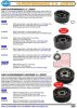
I bolted an inboard CV drive flange from a Ricardo box directly to my 108mm RCR manufactured outboard stub axles today and it matched/fitted perfectly.....I did not try multiple Ricardo parts though, I fear you may have a badly machined component from Ford/Ricardo...as I have in the past.
 
Hi guys, glad to see I was not making a stuff-up! Basically the CV's I have measured have a circle diameter of 93.7mm, close to the standard of 94mm. The Ricardo output flange circle diameter's measure 95.75mm. I will need to try to open up the CV's a little, well by 1.025mm radially to be exact!

The issue will be that there is not much material at the edge of the hole to remove.

CV2.jpg


CV1.jpg


To be exact there is 1.6mm of material before the hole (11mm diameter)breaks through the outer wall of the CV. With M10 bolts (OD of 9.85mm) I could pull this hole elongation back to 0.85mm but I will try for 0.9 to 1mm as it would be good to have a little room.

Well I will get it on the mill this week with an 11mm end mill and see what I can do! Maybe I can make some expensive paperweights to sell on eBay.
 
It`s not big problem. Make holes oval shape in milling cutter, but don`t drill them bigger if you have any doubt that they`ll go thru the wall.
Many competition CV`s are lathed (? dunno right word) for smaller OD to lighten it. Bolt holes are partially open (like in RS500 GrA).
There isn`t much radial or thrust loads.

EDIT: ah, you wrote you`ll mill them, didn`t notice.
 
Last edited:
Hi guys, glad to see I was not making a stuff-up! Basically the CV's I have measured have a circle diameter of 93.7mm, close to the standard of 94mm. The Ricardo output flange circle diameter's measure 95.75mm. I will need to try to open up the CV's a little, well by 1.025mm radially to be exact!

The issue will be that there is not much material at the edge of the hole to remove.

CV2.jpg


CV1.jpg


To be exact there is 1.6mm of material before the hole (11mm diameter)breaks through the outer wall of the CV. With M10 bolts (OD of 9.85mm) I could pull this hole elongation back to 0.85mm but I will try for 0.9 to 1mm as it would be good to have a little room.

Well I will get it on the mill this week with an 11mm end mill and see what I can do! Maybe I can make some expensive paperweights to sell on eBay.
My question is, if there is play in the hole then what centers the cv on the drive flange. if the hole in the cv is 11 mm and the bolt pattern is the same with a 10mm bolt how does it center. it could be off .5 mm. I tried two brands of cv's and one has smaller holes but neither one fits the ricardo hub.
 
The ridges on the outside are how this replacement set came from RCR's supplier, its not a polygroove, looks similar I guess! Fran is checking why, only reason I can see is someone thought they looked "pretty" like this or they were a little lighter (offset some of the mass of that 100,000 pound Ricardo gearbox)! Personally as long as I get them to fit and this does not make them weaker I'm happy.
 
The ridges on the outside are how this replacement set came from RCR's supplier, its not a polygroove, looks similar I guess! Fran is checking why, only reason I can see is someone thought they looked "pretty" like this or they were a little lighter (offset some of the mass of that 100,000 pound Ricardo gearbox)! Personally as long as I get them to fit and this does not make them weaker I'm happy.

the grooves are to make them lighter. the off road guys use them for racing. does not do much for weight. does a lot more for the price they can charge. they do seem to hold up well even with the grooves.
 
As the groove appears to be deep(look at the top pic and the groove is as deep as the bolt holes) me thinks they might be cooling fins to extract heat from the joint.

worse case scenario Jason you can make adapter plates if room permit's.

Jim
 
As the groove appears to be deep(look at the top pic and the groove is as deep as the bolt holes) me thinks they might be cooling fins to extract heat from the joint.

worse case scenario Jason you can make adapter plates if room permit's.

Jim

The regular ones from EMPI are $57 and the lightened ones are $114
 

Attachments

  • 365.jpg
    365.jpg
    44.9 KB · Views: 705

Randy V

Moderator-Admin
Staff member
Admin
Lifetime Supporter
I might have missed it in earlier posts - but - Have you given much thought to machining a drive hub adapter that would bolt properly to the stubs on the diff and than having the CV bolt to the adapter? I'd think that you could make an adapter about 10-11mm thick..
Of course the overall axle length might be a bit of a problem.
Remember that the CV wants to be centered left to right when in the static driving position.
 
After elongating the holes to fit the Ricardo output flanges I wanted to ensure the CV and output flange remained concentric. Elongating holes allows the bolts to bend more than normal and I did not want them to allow the CV to move out of center.

I therefore machined a step in the CV that corresponds to a small machining land on the inside of the transaxle output flange (near the bolt threads). The two parts now lock together perfectly without any movement before the bolts are inserted. All load will now be tangential on the bolts. I'm sure this has not weakened the flange and its only extended the CV length by ~3mm so that will not be a problem. I have also shortened the ball races with this machining operation but if they are out that far I would have to be airborne and I would have more pressing issues to deal with!

I feel a little better now about the CV's I have however if they blow I will replace them with a matched PCD unit. I suggest anyone with a Ricardo measure their output flanges BEFORE getting the inner CV's.

3DSCF3982.jpg


3DSCF3987.jpg

3DSCF3985.jpg

3DSCF3988.jpg
 
Nice work.
I have not decided what to do yet. On my buggy the 930 CV's are held on with 3/8" bolts but the drive flange has a recess that the CV sits in for centering. thinking of trying to neck down the bolts as the 10mm is a little bigger then the 3/8" used on the buggy and they hold up to the 600 hp just fine.
 
Jason, that's a good idea (machining a locking and matching relief). Depending on the relative size of the CV OD v. the flange OD then you might be able to machine another/separate matching relief on/near the OD - I've seen this before and it works well to maintain concentricity.

Looks like you machined the bolt holes to a larger diameter rather than machining an oval shape to accommodate the larger bolt hole pattern, is that correct?

The adapter plate suggestion is a good one as you will be able to maintain the stock CV, bolts holes diameter, and the stock flange and just utilize 12 drilled and threaded holes with differing bolt patterns. As pointed out, you want to maintain a pivot point as near to the lateral pivot point of the suspension to avoid large lateral movement along the CV axle.

As you probably found out, machining CVs is difficult, even with a really good quality mill and lathe given the hardness of the steel typically used for CVs. Better to use an adapter plate of good quality (but not so hard) steel in an appropriate dimension.

Of course, one other possibility is to simply have the holes in the flange welded up and then redrilled on an indexed rotary table on your mill....
 
Thanks for the suggestions Cliff. What I have now is OK. Welding up would be difficult. Unfortunately I could not get to the OD as the outer diameter of the drive flange is identical to the CV.
I first drilled the holes slightly oversize then I milled then elongated them with a 10mm bit as I would have needed a 12.5mm hole to reach the cup PCD and that was out of the question. The problem is you need a long cutter and it bends, tricky for me to do but its done.

And boy are you right that machining CV's is hard. When you hit the hardened area near the races sparks fly off the bit in the lathe! Went through a few bits to get them right!
 
CV Shaft Assembly

Does anyone know if the CV assemblies on each end of a drive shaft need to have the mounting holes aligned or any other requirement? I know the assembly rules of the inner and outer races but just want to know if anything special needs to be followed when aligning the complete CV assembly on the shaft splines?

Thanks in advance.
 
Re: CV Shaft Assembly

Does anyone know if the CV assemblies on each end of a drive shaft need to have the mounting holes aligned or any other requirement? I know the assembly rules of the inner and outer races but just want to know if anything special needs to be followed when aligning the complete CV assembly on the shaft splines?

Thanks in advance.

Check out this site. near the bottom of the page it talks about clocking of the cv CV Assembly
 
Back
Top