
I am starting a thread on my delima of the overheating alternator. This is a 3G alternator, 200 amp. A little background first. The ignition system is the FAST XIM and XFI. These are basicly a plug and play distributorless system. No wiring is mis as they are all labeled and specific as to where they go. So I don’t think anything from this area is mis wired. This is a computer driven system and everything is picked up on the computer. When we first fired the engine up, they noticed that the program wasn’t recognizing the alternator. Everything ran smoothly for the time we ran the engine. All parameters were set and I took the car home. I noticed that the two banks of the exhaust were not even in temps. I also had a leak in a fuel line from the HP pump to its filter. To get to the line I had to remove the alternator. To my surprise it was not hooked up. The fuel line was repaired and the car was taken back to the shop. On hooking it up it was found to be overheating and frying the belt. It was also noticed that the pulley was becoming magnetized. A check with one of the auto electric shops led us to believe that the wiring for the alternator was amis. Took the alternator to the shop and it was converted to a one wire setup which required a new regulator. On checking its output, it was better than the original set up. The original was actually O K, just not as good. After hooking it up and adjusting the butterflys, the car seemed to run O K. We only ran if for a minute or two as it was 8 PM on a Friday. We didn’t hook the computer to it. Probably a mistake on our part. The car was returned home and run a time or two for break in. Occasionally getting the revs up but allowing it to run at an elevated RPM range of around 1200-2000 rpms. Temps were good on both sides this time. Temps got up to 180 and stabilized. It was here that I noticed my tank crossover system wasn’t working as I had hoped. As the tank was nearly empty, I shut it down and let it sit for a while as I needed to check out some other problems. There was an oil leak which I suspect is in a quick connect fitting.
I have the oil and gas lines on quick connects so that when the engine is pulled it is a simple matter to disconnect the lines without all the mess. The water line has a drain line that is used to bleed the system. The size of these lines made the cost beyond what I was willing to pay.
Back to the problem. I reconfigured the fuel overflow line so that for the time being it goes to the primary tank only. I am working on a new system for that. On firing the engine after all this, I worked the idle down to a reasonable range(under 1000 RPM). It was at this time I noticed the smoking and belt squal from the alternator. So I shut it down.
I have been thinking of possible things that would lead to this problem. The alternator is a 3G 200 amp unit from Ford, so I know it should be able to handle the load. Granted I do have a lot of electronics on this engine. Electrical wise I have running at the time, two fuel pumps 6-10 amps each, Spal dual radiator fans of about 13 amps each and an electrical water pump of 20 amps. I had about 9 relays taking care of all the duties. I was not well informed as to the power the relays used themselves. So to run all the coils in the relays I had two relays for just the coils. I have since learned that the coils use about an amp of power. In case you are counting I also have a Mocal trans pump and 7 ½” fan on a cooler which have not been turned on. There is an oil cooler fan as well, but it is controlled via a relay through the American Autowire 22 Highway series fuse box
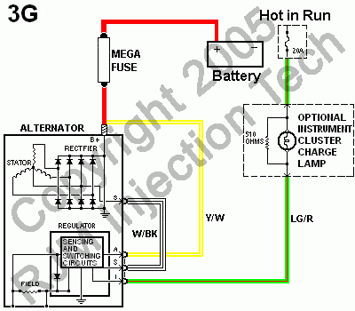
The actions I have taken so far amount to eliminating the two relays to run the coils. A fused supply of 15 amp size will do for the remaining 7 coils and the low fuel lite(one amp signal). It cuts down on the number of wires coming out of the relay box. I am also replacing some other wires that in a quest to keep everything neat I pinched them and they have become shorted out. They were in the turn signals and weren’t being utilized as the rear hatch is off the car. I haven’t fired the car up since the last episode, but probably will tomorrow as I am off then just to see if I have done anything, which electricly is not much. So I expect I will have the same result. Randy has sent me some information, which may help. It is the wiring diagrams for the various alternators that Ford produces. Most include a 510 ohm resister on the optional instrument cluster charge lite circuit. Which of course is not utilized in my circuit. Randy stated that a 510 is near next to impossible to find and a 470 works fine. I am looking into what he has sent and how to check and/or adapt it to my system. I also will be seeking out some info about whether or not it is applicable to my system. So any of you electrical wizards out there, I would appreciate some hints or ideas.
Here is the diagram Randy sent.
Bill
I have the oil and gas lines on quick connects so that when the engine is pulled it is a simple matter to disconnect the lines without all the mess. The water line has a drain line that is used to bleed the system. The size of these lines made the cost beyond what I was willing to pay.
Back to the problem. I reconfigured the fuel overflow line so that for the time being it goes to the primary tank only. I am working on a new system for that. On firing the engine after all this, I worked the idle down to a reasonable range(under 1000 RPM). It was at this time I noticed the smoking and belt squal from the alternator. So I shut it down.
I have been thinking of possible things that would lead to this problem. The alternator is a 3G 200 amp unit from Ford, so I know it should be able to handle the load. Granted I do have a lot of electronics on this engine. Electrical wise I have running at the time, two fuel pumps 6-10 amps each, Spal dual radiator fans of about 13 amps each and an electrical water pump of 20 amps. I had about 9 relays taking care of all the duties. I was not well informed as to the power the relays used themselves. So to run all the coils in the relays I had two relays for just the coils. I have since learned that the coils use about an amp of power. In case you are counting I also have a Mocal trans pump and 7 ½” fan on a cooler which have not been turned on. There is an oil cooler fan as well, but it is controlled via a relay through the American Autowire 22 Highway series fuse box
The actions I have taken so far amount to eliminating the two relays to run the coils. A fused supply of 15 amp size will do for the remaining 7 coils and the low fuel lite(one amp signal). It cuts down on the number of wires coming out of the relay box. I am also replacing some other wires that in a quest to keep everything neat I pinched them and they have become shorted out. They were in the turn signals and weren’t being utilized as the rear hatch is off the car. I haven’t fired the car up since the last episode, but probably will tomorrow as I am off then just to see if I have done anything, which electricly is not much. So I expect I will have the same result. Randy has sent me some information, which may help. It is the wiring diagrams for the various alternators that Ford produces. Most include a 510 ohm resister on the optional instrument cluster charge lite circuit. Which of course is not utilized in my circuit. Randy stated that a 510 is near next to impossible to find and a 470 works fine. I am looking into what he has sent and how to check and/or adapt it to my system. I also will be seeking out some info about whether or not it is applicable to my system. So any of you electrical wizards out there, I would appreciate some hints or ideas.
Here is the diagram Randy sent.
Bill