
You are using an out of date browser. It may not display this or other websites correctly.
You should upgrade or use an alternative browser.
You should upgrade or use an alternative browser.
Keith Baker's Southern gt on the build
- Thread starter Keith Baker
- Start date
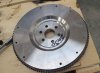
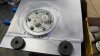
I Fitted the internally balanced flywheel. Thread locked the bolts and torque down at 70 lbs
The main shaft bearing in the crankshaft is fitted, nice tight fit but no bearing sealer used.
Gearbox /AP clutch assy put together, the old AP racing thrust was pressed out as a new adapted version is fitted.
AP clutch has been prefitted but awaiting new bolts, these are M8 cap head, high tensile.
Also waiting for UNF bolts for mounting the gearbox/bellhousing to the engine.
Attachments


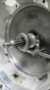
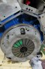
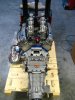
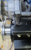
The flywheel has 3 steel locating dowels pressed in and after assembly of the clutch with new m8 high tensile cap head bolts
The gearbox was offered up to the engine.
This slid on like butter and tightened using UNF high tensile cap head bolts.
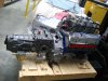
I then attempted to have a trial fit of both engine and box complete into the engine bay but I need a better method of slinging this up on the engine crane so I'm going to have to get some bonds or ropes.
It did go in of sorts but not wanting to damage anything it's better to sling it properly.
I gave good old Frank Catt a call to see if he installed engines with the boxes attached which he does.
What he did remind me of is the need to ensure that the gearbox main shaft does actually go into the crankshaft bearing. The result of not doing so would make for a bad clutch and the need to take all out again.
Therefore being safe than sorry I took the box off and accurately took measurements.
Frank said you need penatration of the shaft in the bearing of around 12mm ..... I have 14mm
" Every body like a good penatration "
Box off , measurements taken and box back on 17 minutes, not bad.
The gearbox was offered up to the engine.
This slid on like butter and tightened using UNF high tensile cap head bolts.
I then attempted to have a trial fit of both engine and box complete into the engine bay but I need a better method of slinging this up on the engine crane so I'm going to have to get some bonds or ropes.
It did go in of sorts but not wanting to damage anything it's better to sling it properly.
I gave good old Frank Catt a call to see if he installed engines with the boxes attached which he does.
What he did remind me of is the need to ensure that the gearbox main shaft does actually go into the crankshaft bearing. The result of not doing so would make for a bad clutch and the need to take all out again.
Therefore being safe than sorry I took the box off and accurately took measurements.
Frank said you need penatration of the shaft in the bearing of around 12mm ..... I have 14mm
" Every body like a good penatration "
Box off , measurements taken and box back on 17 minutes, not bad.
Attachments
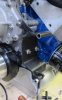
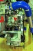
Whilst the engine is out, this is the best time to fit items like the air con pump.
I'm waiting for the alternator and brackets should be next week.
Once these ancillary items are buttoned up I will fit the engine and send it off for the exhaust to be fitted.
The bracket supplied by SGT will need a small modification that's why they supply it with fixings that can be cut to suit.
The pump will NOT run off the same crank pulley groove as shown, I am having a new two groove pulley made.
The front crank pulley will run water pump and alternator and the new inner groove will run the air con. Belt will probably be SPZ 875.
The rear groove in the air con pump will be used and the outer not.
Temporary spacers are fitted until I make the correct size bushes.
Attachments
Hi Keith,
The build is looking fantastic, but just a couple of questions if you don't mind.
Looking back through the build log I notice you have the battery at the front of the car. Are you running a battery strap the full length of the passenger cabin to the starter motor? or are you running another battery in the engine bay area. I really like the idea of having the battery centrally mounted in the front of the car and would like to do somthing similar. If you have any pointers for establishing this sort of set up they would be greatly appreciated.

Thanks Keith, I have the GTD build manual so will be digging it out.
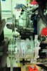
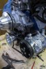
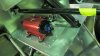
Mounted the air con pump and carried out a few mods to the bracket. SGT said it would need modding a bit.
Firstly the bracket was slightly bent so had to twist it in the vice.
Cut the top so as to allow the pump to align with the pulley.
This is not the pulley it will eventually be on but it should align with the inner one when made.
Spacers made to exact size, Bingo.
Will get this powder coated later.
had to trim a small amount off one of the air con pump fixing lugs that's not used to get the pump to swing closer to the engine.
This allowed me to drop a belt size down to SPZ850 and more adjustment
Trying to work out a good way to mount the oil pressure & tempreture sensors directly on the engine.
Fitted the last of the ally trims. No more funny angles to work out and cut.
Attachments
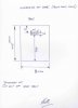
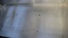
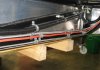
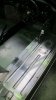
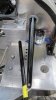
When trying to fit the fuel sensors into the tanks it became apparent that a sensor with 6 fixing holes would not fit on a tank with 5 holes.
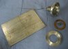
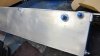
A modification was required therefore two new mounting plates were made that will be welded over the existing holes in the tank The sensor will sit within a recess.
Care was taken to watch for clearance of the top of the sensor to the underside of the panel, hence the recess.
I only had a thick plate of ally so a fair bit of lathe work was needed.
This may seem like it's not a huge thing to put on the build log but it solved a problem but if you aint got a lathe it would be even bigger headache.
Whilst the tanks are out AGAIN I will be welding in a fitting for a breather and roll over valve.
" Not that I want it to roll over "
Attachments
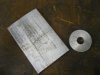
Collected the tanks back from welding I need to tidy up and flush the tanks through with water to remove any swarf etc and also to ensure there leak free.
The welder does a seriously neat job and charges a fair price.
( Metal prefabrications, Dartford , Kent. UK )
I did think about getting a welder for ally but I dont think I'd use it enough.
Also wired in the fuel pumps. As I have a pump low level on each tank and the wiring is for both pumps on one side I had to cut into the loom and re route the wiring.
H.P. filter and alternator arrived so will get those installed.
What gets my goat is I have an alternator kit from the USA and all the fixing plates are different threads to the bolts they supply with it. It's a nicely finished package but I'll have to re drill 5 of the 6 fixings, also the adjuster arm holes are wrong. Do these people not piece it together before they market it !
The new front nostril panel arrived also, mine was touching the ally panelling, this fits but the horn is in the way, have to move it.
2 steps forward, one back.
Pictures to follow
Refitted the tanks after modifying the sender positions and installing a central air bleed -8 fitting.
Conflicting info about where the bleed should be so now I have one in the middle and one at each end just in case.
The intention is to fit the -8 breather pipes with roll over valves.
I have also found that one of the BG fuel pumps I have is defective,
I was trying to use the 2 pumps I had as they have always coped with the flow for bigger output engines and as I had them it was the most cost effective option.
Now that one is dead, I have decided to install 2 new pumps in a different position... So" All change " another alteration.
Due to the engine output and the High Pressure pumps supplied by the engine man I have got to position these to be functional and as tidy as possible.
the last 2 pictures are not the finished item but yet another a pre fit.
Attachments
Terry Oxandale
Skinny Man
Looks good Keith! When I welded my tanks, I found (purely by accident) that the water did not show the leaks I had, but that mineral spirits did. I wished I could send my 10 gallons of them to you, 'cause after I tested the fuel system with it, it's useless (unless somebody has an alternative use of it?).
Tanks all finish ( I think ).
New L.P. fuel pumps and filters arriving today.Been a bit of a quite week on the car.
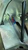
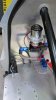
I decided to install an air vent at the rear of the spider so I cut a round hole into the roof of 100mm diameter and with the help of a buddy made from a solid billet of ally a nice looking sleeve to go into the cockpit rounded edges in case of IVA
although you can't see much of it which is a shame.
The top will be covered with a two row of 4 or 5 louvre grill made by a fabricator I know. I may be wrong but generally only Mk 11 's had the grille but I have seen a few Mk1's with this and it adds a bit
I will post pictures when I have them.
The car is going on a holiday for a couple of weeks to have some nice ally panels made. rear defuser for mounting oil coolers etc and a few other bits as well.
I can concentrate on the engine which was planned to be in by now but others have thrown a spanner in the works.
New L.P. fuel pumps and filters arriving today.Been a bit of a quite week on the car.
I decided to install an air vent at the rear of the spider so I cut a round hole into the roof of 100mm diameter and with the help of a buddy made from a solid billet of ally a nice looking sleeve to go into the cockpit rounded edges in case of IVA
although you can't see much of it which is a shame.
The top will be covered with a two row of 4 or 5 louvre grill made by a fabricator I know. I may be wrong but generally only Mk 11 's had the grille but I have seen a few Mk1's with this and it adds a bit
I will post pictures when I have them.
The car is going on a holiday for a couple of weeks to have some nice ally panels made. rear defuser for mounting oil coolers etc and a few other bits as well.
I can concentrate on the engine which was planned to be in by now but others have thrown a spanner in the works.
Also and importantly I have been in conversation with Quiafe regarding my brand new ZFQ.
Apparently there has been some issues with the ZFQ although not many and I have a reply from them regarding an upgrade.
At £ 800 a decision is to made whether to do this now or potentially have a bigger problem. I will post Quiafe's reply letter on the transmission section of the forum very shortly.
Fitted all the panels under the cills with Dynamat sound deadening.
I must say this is good stuff to fit, easy to cut and sticks really well.
Hope it does what it says on the packet !
Also all the internal trims now fitted to tidy any sharp edges that could be a IVA problem.
Same trim all over the car.
I must say this is good stuff to fit, easy to cut and sticks really well.
Hope it does what it says on the packet !
Also all the internal trims now fitted to tidy any sharp edges that could be a IVA problem.
Same trim all over the car.
Attachments
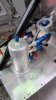
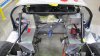
New fuel parts arrived today so trial fitted everything together and made up 80% of the hoses.
Have ditched the BG pumps in favour of new Aeromotive L.P. & H.P. pumps, filters and billet brackets.
So the setup is :
From each of the tanks into a Aeromotive 100 micron filter.
Into the Aeromotive 150 GPH fuel pumps
Into the swirl pot.
Then go into 1 Aeromotive 10 Micron filter and then
into 1 Aeromotive A1000 H.P. pump
Still got to fit solenoid valves in the system somewhere
Made a plate up to take all this fuel gear.
Attachments
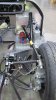
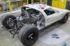
Had a couple of hours on the car today. It's going in the morning to have some fabrication work etc. So it's strip all the bits off that are going to the polishers like water expansion tank, swirl pot etc.
Also a few parts powder coated. Had to modify the seat belt bracket as the holes were out by about 10mm so welded the holes and milled out new ones.
Strip out the fuel system.
Looks like I have gone back 4 months.
Time to finish the engine and possibly get the box upgraded at Quiafe's which is only 10 minutes from me.
Attachments
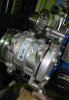
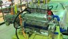
I had to Modify the alternator bracketry to align with the rest of the pulleys, it's amazing how you buy factory made bracketry and all the fixings and most of the bolts they supply dont even fit together. Surely they test there own products ?
Made a 102mm spacer from heads to alternator.
Nice looking brackets though. ( March racing products)
I had to have another crankshaft pulley made for the drive for the air con unit. This aligned perfectly and I have maximum adjustment available.
All the fuel lines will be in stainless Goodrich and the oil lines the same but with the black braiding over and black speedflow fittings.
Just arrived is the in line oil thermostat, that's going in line to the rear oil cooler.
The sandwich block also has a take off for the capillary oil presure gauge
Attachments
Similar threads
- Replies
- 2
- Views
- 331
- Replies
- 32
- Views
- 3K