Nice brackets for the coil, I'm gonna steal that!

You are using an out of date browser. It may not display this or other websites correctly.
You should upgrade or use an alternative browser.
You should upgrade or use an alternative browser.
GTD40 Restoration
- Thread starter Skorpion
- Start date
Hi Pete,
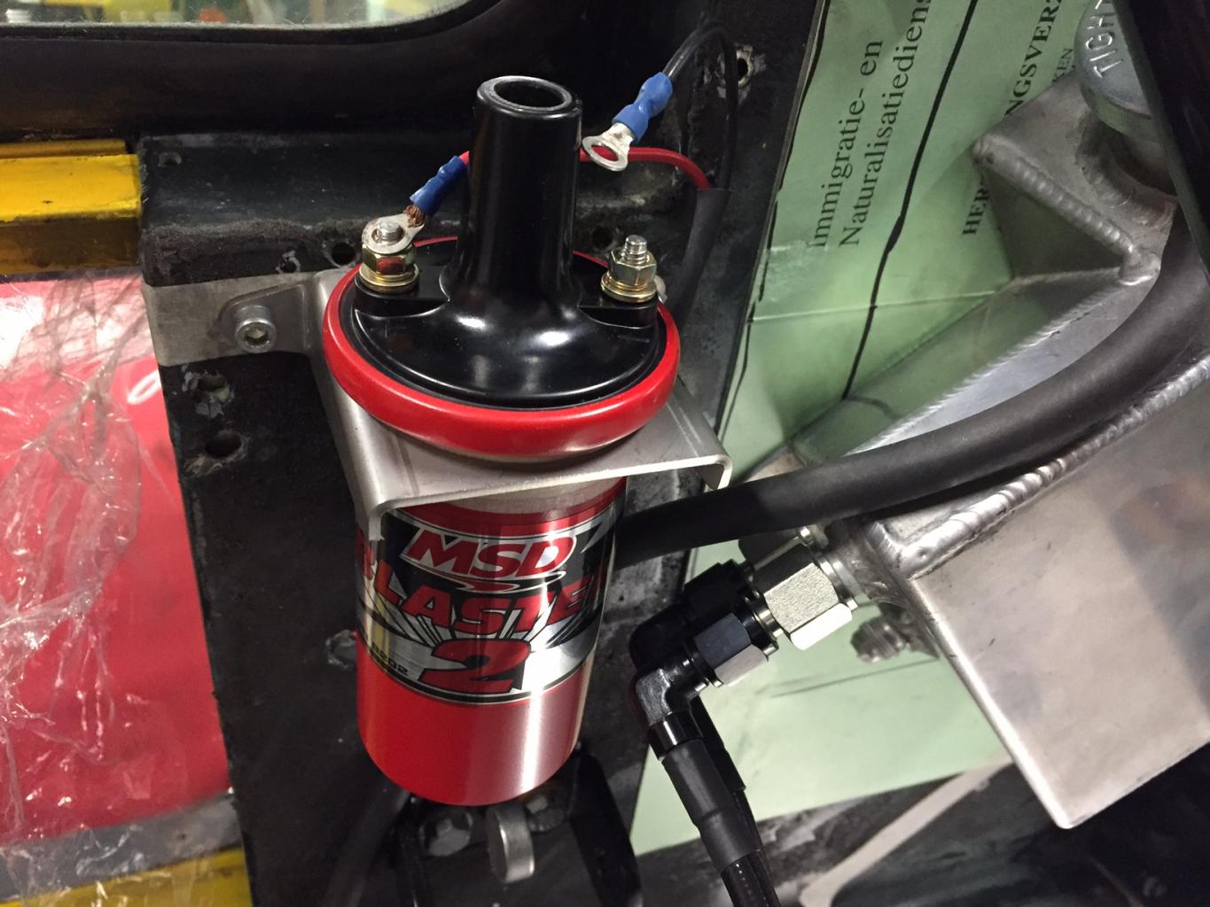
Hereby the latest picture.
Using one bracket alone is okay but hinges too much on a too short section so the height of the foot should be bit heigher for better support.
I also mounted a backplate behind the wall to connect both brackets to a more rigid structure so the set in total is a stiffer unit.
Attachments
Mike Pass
Supporter
Hi Andy,
I see from your radiator pic that you have bolted the radiator in without any rubber to flex. The chassis do flex and this can stress the radiator if it solidly bolted to the chassis which may cause it to leak at the joints. I have my radiator mounted on rubber bobbins which allow the rad to float and avoid flex stress from the chassis. The small rubber mountings with a screw thread at each end do the job well. The radiator should be able to be moved slightly by hand.
Cheers
Mike
Hi Mike,
Your are correct and I was aware of this issue reading all the bad experiences with leakages on radiators. Also it depends on the type of radiator, some seems more proun to leak than others due to flex of the chassis.
The gtd40 radiator is a snug fit and there is no space for the rubber mounts.
The concept which I am thinking of is removing the welded plate on one side and make a floating bracket so the radiator is fixed on one side snug and able to slide in the bracket on the other side.
Looking to the current connection, there is some flex possible but not much. Another solution could be to make the current bracket more flexible allowing to absorb the movements.
To be continued.
Regards
Andy
Brett James-McCall
Moderator
Andy,
See what I did with mine here: http://www.gt40s.com/forum/gt40-build-logs/15571-bretts-rs-gtd-10.html#post396291
Brett
See what I did with mine here: http://www.gt40s.com/forum/gt40-build-logs/15571-bretts-rs-gtd-10.html#post396291
Brett
Thanks Andy!
Hi Brett,
You have a good solution to support the radiator.
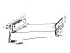
I have already isolated and paneled the inner sides so try to avoid tearing it apart again.The solution I am thinking of....
One side is fixed as normal, the other side is able to move and twist.
You have a good solution to support the radiator.
I have already isolated and paneled the inner sides so try to avoid tearing it apart again.The solution I am thinking of....
One side is fixed as normal, the other side is able to move and twist.
Attachments
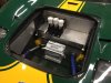
Mounted the King fuel pressure and filter unit.
Lot of work for such a simple bracket but glad it is done.
Why do the inlet and outlet always point the wrong direction with these units having to make awkward brackets ? ;O)
Cleaned up the front and the rear section.
Lot of work for such a simple bracket but glad it is done.
Why do the inlet and outlet always point the wrong direction with these units having to make awkward brackets ? ;O)
Cleaned up the front and the rear section.
Attachments
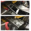
Mounted the ignition control box to the inside chassis bulkhead on an aluminium bracket springloaded on the 2 bolts holding the top bracket of the top long suspension rod. The lower section of the bracket is supported by rubber.
Next job is to make new brackets for the radiator.
Next job is to make new brackets for the radiator.
Attachments
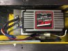
Mounted the ignition control box to the inside chassis bulkhead on an aluminium bracket springloaded on the 2 bolts holding the top bracket of the top long suspension rod. The lower section of the bracket is supported by rubber.
Have you done that to minimise vibration Andy? I thought those things were all encapsulated these days but I could be wrong...
Brett James-McCall
Moderator
The MSD units come with anti vibration feet
Brett
Brett
Brett James-McCall
Moderator
The MSD units come with anti vibration feet
Brett
Brett
Brett James-McCall
Moderator
Andy, personally, I would just take a 5mm drill bit and widen the mount holes slightly and then buy these: 4pcs M5 Male Female Anti Vibration Rubber Mounts Isolators 15mm x 15mm | eBay
That's all they are on the MSD, just get some M5 pan head machine screws and spring washers and you should be good to go.
Brett
That's all they are on the MSD, just get some M5 pan head machine screws and spring washers and you should be good to go.
Brett
Hi Brett,
Had initial the same solution as you prescribed. Didn't want to wait for those small items and besides, they become quickly very expensive (exchange rate is not in my favor at the moment) and overseas shipment cost is 10 pounds for these small items. Sometimes need to be inventive to move on
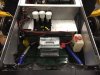
Started working on the power cables.
I noticed most gtd40 tend to route also the (-) to the rear of the car close to the engine. Why not hook it direct to the chassis in the front of the car close to the battery ? I measured the resistance being only 0.1 Ohm between a front and rear chassis connection point. What am I missing here ?
Regards,
Andy
Had initial the same solution as you prescribed. Didn't want to wait for those small items and besides, they become quickly very expensive (exchange rate is not in my favor at the moment) and overseas shipment cost is 10 pounds for these small items. Sometimes need to be inventive to move on
Started working on the power cables.
I noticed most gtd40 tend to route also the (-) to the rear of the car close to the engine. Why not hook it direct to the chassis in the front of the car close to the battery ? I measured the resistance being only 0.1 Ohm between a front and rear chassis connection point. What am I missing here ?
Regards,
Andy
Attachments
Brian Magee
Supporter
I my experience, most GTD's take the earth (-) side of the battery to the top N/S mounting bolt of the anti-roll bar (about 9"long).
Brian,
Brian,
 leased:
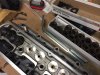
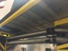
Stiffened the side skirt floors above the fuel tanks with an aluminium plate and riveted T-profiles. Quite stiff now.
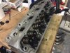
Borrowed a better tool to install the head springs. Good tools are half the work they say.
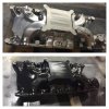
Painted the inlet manifold since the chromed powder-coat was ugly. It should dry up with a wrinkle effect. We will see how it dries up.
The new rods and pins are somewhere between the States and Europe so the balance job is on hold for a few weeks.
Finished the wiring in the front section of the car.
The wiring in the rear sections is almost done.
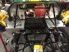
And the car is back on its feet.
Borrowed a better tool to install the head springs. Good tools are half the work they say.
Painted the inlet manifold since the chromed powder-coat was ugly. It should dry up with a wrinkle effect. We will see how it dries up.
The new rods and pins are somewhere between the States and Europe so the balance job is on hold for a few weeks.
Finished the wiring in the front section of the car.
The wiring in the rear sections is almost done.
And the car is back on its feet.
Attachments

Similar threads
- Replies
- 6
- Views
- 449
- Replies
- 9
- Views
- 2K