
You are using an out of date browser. It may not display this or other websites correctly.
You should upgrade or use an alternative browser.
You should upgrade or use an alternative browser.
Coolant hose routing on SBF Ford... How'd you do it?
- Thread starter 84Venom
- Start date
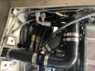
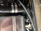
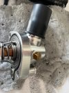
Joe, it’s very difficult to show clear routing photos because of the tight and congested spaces involved. Here are a few that may help.
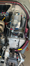
Also included a photo of my expansion tank, but again, not easy to understand the hose routings. The upper left fitting is the vent line from top of radiator and steam relief from rear of heads. Below that is the rubber hose to the second water pump outlet. Underneath the tank is the 1/2” AN line that connects to a tee going into the water pump inlet. The upper right fitting obviously goes to the overflow/recovery tank.
Also included a photo of my expansion tank, but again, not easy to understand the hose routings. The upper left fitting is the vent line from top of radiator and steam relief from rear of heads. Below that is the rubber hose to the second water pump outlet. Underneath the tank is the 1/2” AN line that connects to a tee going into the water pump inlet. The upper right fitting obviously goes to the overflow/recovery tank.
Attachments
Michael, what a great idea I’m stealing for the drain petcock location! If able, I’ll tilt mine down as far as possible (albeit clearance issues) to aid in a clean draining process.Joe, it’s very difficult to show clear routing photos because of the tight and congested spaces involved. Here are a few that may help.
Also included a photo of my expansion tank, but again, not easy to understand the hose routings. The upper left fitting is the vent line from top of radiator and steam relief from rear of heads. Below that is the rubber hose to the second water pump outlet. Underneath the tank is the 1/2” AN line that connects to a tee going into the water pump inlet. The upper right fitting obviously goes to the overflow/recovery tank.
Has anyone tried or have negative thoughts on having an under engine cover to aid in a smooth belly pan?
Thanks Michael. Looks like a combination of 90 degree hoses and couplers for the large hoses. I assume you just buy random sections off the shelf that will fit and couple them together? Also, any pics of the upper intake fitting ( looks like 90 degrees)? So the smaller water pump fittings just go back and forth to the expansion tank? Thanks so much for the info!!Joe, it’s very difficult to show clear routing photos because of the tight and congested spaces involved. Here are a few that may help.
Also included a photo of my expansion tank, but again, not easy to understand the hose routings. The upper left fitting is the vent line from top of radiator and steam relief from rear of heads. Below that is the rubber hose to the second water pump outlet. Underneath the tank is the 1/2” AN line that connects to a tee going into the water pump inlet. The upper right fitting obviously goes to the overflow/recovery tank.
Bill Kearley
Supporter
Oil cooling = no belly pan.
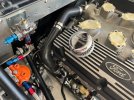
Joe, I actually utilized a variety of 90s, 45s (some with 4” legs, some with 6” legs) and straight sections, plus you’ll need several aluminum couplers all of which are available at Pegasus. You can pretty much do everything with those OTS pieces.Thanks Michael. Looks like a combination of 90 degree hoses and couplers for the large hoses. I assume you just buy random sections off the shelf that will fit and couple them together? Also, any pics of the upper intake fitting ( looks like 90 degrees)? So the smaller water pump fittings just go back and forth to the expansion tank? Thanks so much for the info!!
The upper intake fitting is a billet aluminum swivel unit, which makes it far easier to route the hose.
The upper water pump fitting is for the t-stat bypass hose, the other goes to the expansion tank.
Attachments
Ian Anderson
Lifetime Supporter
Paul Walton ran an aluminium belly pan on his Tornado GT40
Things did get hot and from memory he lost his speedometer as the sensor got too hot
Changed the rear 4 hole Le Mans style vents for MK2 type mesh for more airflow
He also started making some naca ducts to channel air towards things like alternator, fuel pump etc….not sure how he got on with that
Ian
I just worked through this on my SPF:
I have some left over unused couplers, silicon hoses, and Gates power bands for a deal...but they are 1000 miles away and are a few months from being visited. If your project timeline allows it and you are interested...
I was in my garage and found a GT40! It is one I have owned for some 17 years, but rarely drive. I made my mind up to change that this coming year and decided to move it to another outbuilding where I will see it more often and give it the attention it deserves. Basically a "barn find" in need of love. It is a SPF with Roush carb'd 427.
I got it to start, run, and to idle (it had been months since the last startup). While watching the coolant temp it took a little while to register (a normal amount of time as I remember it), then it started it's normal "slow-ish" climb rate. As it...
I got it to start, run, and to idle (it had been months since the last startup). While watching the coolant temp it took a little while to register (a normal amount of time as I remember it), then it started it's normal "slow-ish" climb rate. As it...
- SpyderMike
- Replies: 251
- Forum: GT40 Tech - Fueling, Electrics, & Engine Cooling
I have some left over unused couplers, silicon hoses, and Gates power bands for a deal...but they are 1000 miles away and are a few months from being visited. If your project timeline allows it and you are interested...
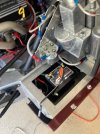
So ive gotta ask, whats under the lexan window? I assumed thats where the battery goes, but i could be wrong....Joe, it’s very difficult to show clear routing photos because of the tight and congested spaces involved. Here are a few that may help.
Also included a photo of my expansion tank, but again, not easy to understand the hose routings. The upper left fitting is the vent line from top of radiator and steam relief from rear of heads. Below that is the rubber hose to the second water pump outlet. Underneath the tank is the 1/2” AN line that connects to a tee going into the water pump inlet. The upper right fitting obviously goes to the overflow/recovery tank.
Hi Mike, what fittings do you have left?I just worked through this on my SPF:
I was in my garage and found a GT40! It is one I have owned for some 17 years, but rarely drive. I made my mind up to change that this coming year and decided to move it to another outbuilding where I will see it more often and give it the attention it deserves. Basically a "barn find" in need of love. It is a SPF with Roush carb'd 427.
I got it to start, run, and to idle (it had been months since the last startup). While watching the coolant temp it took a little while to register (a normal amount of time as I remember it), then it started it's normal "slow-ish" climb rate. As it...
- SpyderMike
- Replies: 251
- Forum: GT40 Tech - Fueling, Electrics, & Engine Cooling
I have some left over unused couplers, silicon hoses, and Gates power bands for a deal...but they are 1000 miles away and are a few months from being visited. If your project timeline allows it and you are interested...
I don't have a specific list on me right now, and, as mentioned, I am quite a distance away. I can try to look at purchases and derive a approximation though...
I had enough to change to all silicon with metal couplers. I ended up buying the big steel pipe from Hillbank and used that instead.
I had enough to change to all silicon with metal couplers. I ended up buying the big steel pipe from Hillbank and used that instead.
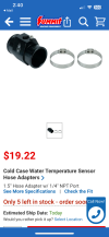
I looked at that Cold Case fitting that you put the drain into. Website says its only 1-1/4". Any issues with leaks using 1-1/2" hoses?Yep, a lightweight Braille AGM.
I know I have some (probably 6) Pegasus
And I am guessing a couple of 1-3/4" silicon 45s and maybe a 90 degrees. I also have two 5/8" silicon 90s. Then there are a bunch of Gates PowerGrip 32954 and 32925 and probably 32948 Hose Clamps...
| HJ45 | 45mm (1 3/4 inch) Pegasus Pro Design Aluminum Hose Joiner |
And I am guessing a couple of 1-3/4" silicon 45s and maybe a 90 degrees. I also have two 5/8" silicon 90s. Then there are a bunch of Gates PowerGrip 32954 and 32925 and probably 32948 Hose Clamps...
TS38 is the one I bought, 1.5”I looked at that Cold Case fitting that you put the drain into. Website says it’s only 1-1/4". Any issues with leaks using 1-1/2" hoses?
Attachments
Ha. Go figure. I was on the Cold Case site and they only showed the 1.25. Thank you!!!!TS38 is the one I bought, 1.5”
Howard Jones
Supporter
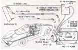
Thanks Howard. Great info!!Here:
Do you have questions about it? Ask away. Oh, raise the expansion tank as high as it physically fits under the bodywork.
Similar threads
- Replies
- 19
- Views
- 2K
- Replies
- 9
- Views
- 1K