
You are using an out of date browser. It may not display this or other websites correctly.
You should upgrade or use an alternative browser.
You should upgrade or use an alternative browser.
Classic HorsePower Scratch GT40
- Thread starter Wolfman
- Start date
G86.20 Boxster S 6 speed. With the AP design rear suspension, there are a few challenges but the biggest positive was the cost and gear ratios with the extra gear. The biggest negative is that the engine sits about another inch or so higher (the transaxle drain plug is the lowest point) as the oil pan is about an inch or so above the bottom frame rails. It will be mostly street driven and only on a track for an occasional/rare outing.Which transaxle are you using?
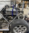
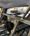
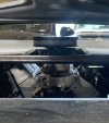
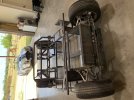
Dropped in the motor & trans today. Things are looking pretty much as planned and expected. Will have some trimming to do on the GW valve cover oil filler neck to stay below contact with the clamshell, but the top of the covers themselves are about an inch+ from touching. I tried the largest air cleaner I have and it will clear both the bulkhead window and the back “glass”. I think I will source a smaller sized one down the road.
Attachments
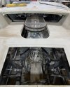
I don’t have a direct pic looking in/out of the bulkhead window. That air cleaner certainly fills the space without being too thick. Here’s a couple other pics from different angles and will get the direct shots after work today.Do you have a picture of what your air cleaner area is going to look like when the car is done and you are looking through the rear clam glass? I keep going back and forth between a MPFI 8-stack and a MPFI/carb set up. Your air cleaner may be the answer to the "WOW" factor needed.
I am thinking of building a custom “turkey pan” to help direct more air into the cleaner and have to build a custom hump where I’ve cut the deck near the rear window behind the air cleaner. This was necessary to make room for the exhaust manifolds which have a high pipe due to the crossover.
Attachments
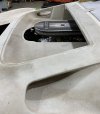
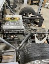
Ok a couple more pics. The rear part of the back window stops just below the air cleaner top. Just for reference, I have the 40 on my four post lift which makes it about a foot in the air and my Chevy 2500 is about a car length behind it.
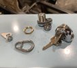
Ordered and just got delivered today a set of Lotus Europa bonnet locks from a supplier in the UK. Overall I’m pleased with the quality and options on how to mount it and adapt to work with my bear claw latches and handles. More to come on this soon.
Ordered and just got delivered today a set of Lotus Europa bonnet locks from a supplier in the UK. Overall I’m pleased with the quality and options on how to mount it and adapt to work with my bear claw latches and handles. More to come on this soon.
Attachments

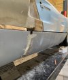
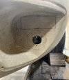
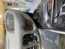
Well it was time today to “weld” the side sill covers into final length and form. They were 66” in length (widest point wheel opening to wheel opening) and supposedly taken from a skin mold of an original car. Even though the original wheel base was 95” and splitting my skin around the spider to rear clamshell opening, I’ve found with my 97” wheelbase that I only needed to lengthen the sill about 1.25” with a slight angle outward to match the flare of the rear wheelwells. This leaves the wheels looking perfectly centered in the front and rear openings and having stock length spider, doors and front clamshell. In the end it “looks right” and would hope anyone looking at it without a side to side comparison to find where the extra 2” of the wheelbase comes from.
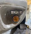
Also had time while the epoxy was curing to locate and cut the rectangular fog lights just above the Lucas turn signals.
Also had time while the epoxy was curing to locate and cut the rectangular fog lights just above the Lucas turn signals.
Attachments
Last edited:
Side sill graphed together incorporating the stretch. Lines are starting to come together (albeit rough) and will be good enough to go to bodywork stage. Next will be an upper door splice to correct the windshield to upper door line. I’m still amazed how the various sources of all these panels vary as much as 1/2” in different areas.

Last edited:
Mark Turner
Supporter
Looks like you are doing a great job making it all fit together!
So i decided it was time to address the AC system and what I am going to do with the v-belt, alternator, and air conditioning compressor. After lots of research and seeing what’s commercially available (and lots of suggestions here), I called CVF Racing and ordered their 302 ACO system. It uses a shorty water pump and Sanden 508 compressor…mounted high on the drivers (LH) side. Needless to say, I will be modifying that to try and alter it to a mid or low mount arrangement.
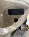
Also ordered a “compact” evaporator & heater unit. To make it fit with as high a mounting position and clearance from my accelerator pedal & foot, again modification was needed to the side mounting posts and the variable speed heat sink relocated. In addition, an upper mounting frame was made to take advantage of the available space above the front chassis structure and clam shell which will eventually covered with a fabricated aluminum panel. This unit has 6 ports so 2 will go to the dash vents, 2 for underdash (hidden) foot vents, and one/two for the defrost windshield demister. The upper AC support enables unbolting of the assembly to ease in mounting and any maintenance down the road.


Also ordered a “compact” evaporator & heater unit. To make it fit with as high a mounting position and clearance from my accelerator pedal & foot, again modification was needed to the side mounting posts and the variable speed heat sink relocated. In addition, an upper mounting frame was made to take advantage of the available space above the front chassis structure and clam shell which will eventually covered with a fabricated aluminum panel. This unit has 6 ports so 2 will go to the dash vents, 2 for underdash (hidden) foot vents, and one/two for the defrost windshield demister. The upper AC support enables unbolting of the assembly to ease in mounting and any maintenance down the road.
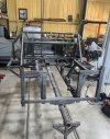
Decided that it was time to blast it all apart and accomplish the final welding of the chassis, prep & paint, and installing some of the paneling before going further with the build. So back onto the rotisserie it goes…
Attachments
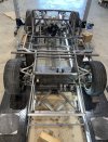
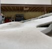
It’s been HOT here in west Texas the last couple of months but was able to get the last bit of finish TIG welding done and chassis prepped for primer. This morning I was able to get it sprayed in metal etch 2K primer.
Next on the plan is to start on underside paneling, specifically the floor pan, cockpit side panels and behind the seat bottom panels.

Next on the plan is to start on underside paneling, specifically the floor pan, cockpit side panels and behind the seat bottom panels.
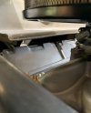
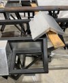
Since my mind has shifted to the paneling of the chassis, I have rediscovered aluminum honeycomb panels and am thinking about using it for the bulkhead access panel (approximately 26”x17”) and possibly the two panels either side of it. Since this is directly behind the seat, I want the best insulation from heat, sound, and something solid for safety and isolation from the engine in the event of any fire or accident.
Anyone have personal experience with working with or using these panels in this application and can recommend or have a better idea?

Anyone have personal experience with working with or using these panels in this application and can recommend or have a better idea?
I have only used the honeycomb panels, composite or metal cladded for false bulkheads and flooring in aircraft. Even the composite versions are heat tolerant and help with noticeable noise reduction. Sure the resins are much more expensive and specific to the application, but i believe it would help.
The metal sided ones though would most likely not help insulate but I believe would trasfer the heat more acting as a heat sink.
The metal sided ones though would most likely not help insulate but I believe would trasfer the heat more acting as a heat sink.
Douglas…you think Aramid honeycomb panel would be better then? Is it paintable? I take it that a 3M panel bond adhesive would be best used to secure aluminum strips to use as a fastening surface/frame/tabs?I have only used the honeycomb panels, composite or metal cladded for false bulkheads and flooring in aircraft. Even the composite versions are heat tolerant and help with noticeable noise reduction. Sure the resins are much more expensive and specific to the application, but i believe it would help.
The metal sided ones though would most likely not help insulate but I believe would trasfer the heat more acting as a heat sink.
Devin
Aramid fiber is a good insulator of electricity and heat and is resistant to organic solvents, fuels, and lubricants.Douglas…you think Aramid honeycomb panel would be better then? Is it paintable? I take it that a 3M panel bond adhesive would be best used to secure aluminum strips to use as a fastening surface/frame/tabs?
Devin
View attachment 141726
Or just use good ol' regular sheet metal and Thermo-Tec acoustical and heat control mats and thin carpet for a clean appearance.
All really just want you want to spend money on and what personal preference you want.
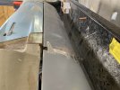
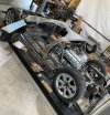
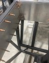
With long weekends comes progress (usually). I have started making and drilling for my spaceframe panel installation. Floor pan, cockpit sponson side panels, rear seat bases (lower bulkhead), and half of the engine bay side sponson panels are fabricated. I’m actually enjoying the challenge of making these and getting to use tools I’ve collected just for this build (30” combo shear/brake, hydraulic hole punch, bead roller, etc).

Attachments

Neil
Supporter
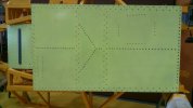
Looks vaguely familiar...but I only have 451.Finally added Avex rivets to the panels and sealed with 3M 5200 Marine Adhesive yesterday. Approximately 550 pops later, she is ready to flip back over and continue with more panel making.
View attachment 141878
Attachments
Similar threads
- Replies
- 5
- Views
- 3K
- Replies
- 53
- Views
- 10K