Another Fuel Pump Thread!

Howdy All!

Actively planning an RCR build while waiting on kit delivery.

I keep going back and forth on a fuel system design. I plan on using a simple "returnless" fuel system feeding a Holly 4bbl @ 6PSI. The engine is rated at less than 500HP, so theoretically 41GPM is required at continous WOT.

I have combed the various threads on fuel pumps - types / flow rates / arrangments, each with various pros and cons in regards to noise, performance, reliability, simplicity, and aesthetics.

During my planning / research I noticed no one has discussed this type of pump...

Pump.jpg


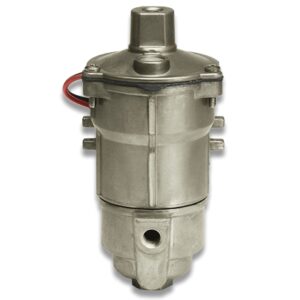
This Walbro pump is rated at 43gpm, has an internal 70micron suction filter, can dry lift 48in, and has an internal check valve.

While not period correct, I do think this pump would be somewhat aesthetically pleasing if installed in a similar arrangement to the original car(s).

Does anyone have experience with this style Walbro pump? Stewart Warner has something near idenitcal, but with less features.
 
Brandon, most of us are using Facet or Holley, what are the pro and con that conduct you to this choice.
I am using 2 Facet BlueTop on 482 big block since 15 years without any problem.
 

Ian Anderson

Lifetime Supporter
Do you know if it is lake the Facet (tick tick tick) type of pump or a rotory vane type

If the latter they do not normally like running dry and will get noisy very quick. And with the long narrow tank in a GT40 they will suck air as the fuel sloshes forward under braking
ian
 
Looks like a nice pump that has a somewhat period correct look to it!
Agree!
Do you know if it is lake the Facet (tick tick tick) type of pump or a rotory vane type

If the latter they do not normally like running dry and will get noisy very quick. And with the long narrow tank in a GT40 they will suck air as the fuel sloshes forward under braking
ian
Ian, I believe these are not a rotory vane type but rather a piston style pump. This is what is started on their website:

"These pumps incorporate a new piston mechanism which, unlike rubber diaphragms, is not affected by modern, high-tech fuel blends."

Walbro also claims on their site:

"Continuous duty life (diesel fuel): >18,000 hours / Can run dry for up to 4 hours"


I wanted to avaid a rotory vane if possible for two reason: 1. Very loud during operation 2. The need to me mounted at tank level.

I do have concrens for sloshing fuel in the tanks, I plan on addind baffels with these trap doors:


Screenshot_20241220_231708_Chrome.jpg
 
As I've spent the last week looking into carbureted fuel pumps this is very interesting.
I considered the Walbro FRB5-1 as a potential but discounted it for the following reason :

The pump has a flow of 170 litres (45 GPH) and a pressure of 8.0-11.0 PSI.
My engine will be in the 400 BHP area so a flow rate requirement of 30 GPH - Edelbrock carb being used so looking at this flow rate being at approximately 6.5 PSI.
I can't find a flow at pressure chart for this pump but knowing that flow reduces as pressure increases I put this into the "more research required" category and have continued the search.

However, having looked at bit closer at the Walbro specs. it now seems that the flow rate of 170 litres is defined as being "Minimum Flow Rate" - presumably at the 8.0 PSI lower value.
Most manufacturers seem to promote the pumps with max flow at minimal pressure.

The Walbro product for me is either perfect or there's a typo on the spec. information.


In the UK this is available for £120.00 including VAT.
MarkR

Looks like the main difference between the FRB5-1 and FRB13-2 is the added internal fuel filter which would explain the slight performance difference as well unless I am missing something else. These will be at the top of my list when I comes to that point of my build as I’m going carb on a 347 stroker.

The biggest question is one per tank (plumbed prior to valve selector) or one only with my manual tank valve selector prior to the pump.

Good find you all.
 
Last edited:
As I've spent the last week looking into carbureted fuel pumps this is very interesting.
I considered the Walbro FRB5-1 as a potential but discounted it for the following reason :

The pump has a flow of 170 litres (45 GPH) and a pressure of 8.0-11.0 PSI.
My engine will be in the 400 BHP area so a flow rate requirement of 30 GPH - Edelbrock carb being used so looking at this flow rate being at approximately 6.5 PSI.
I can't find a flow at pressure chart for this pump but knowing that flow reduces as pressure increases I put this into the "more research required" category and have continued the search.

However, having looked at bit closer at the Walbro specs. it now seems that the flow rate of 170 litres is defined as being "Minimum Flow Rate" - presumably at the 8.0 PSI lower value.
Most manufacturers seem to promote the pumps with max flow at minimal pressure.

The Walbro product for me is either perfect or there's a typo on the spec. information.


In the UK this is available for £120.00 including VAT.
Good follow up info and context!

MarkR

Looks like the main difference between the FRB5-1 and FRB13-2 is the added internal fuel filter which would explain the slight performance difference as well unless I am missing something else. These will be at the top of my list when I comes to that point of my build as I’m going carb on a 347 stroker.

The biggest question is one per tank (plumbed prior to valve selector) or one only with my manual tank valve selector prior to the pump.

Good find you all.
MarkR, my plan was to run a pump per tank. While this does increase cost, a pump per tank adds redundancy and reliability. Switch tanks by switching which pump has power. My question is do I want to mount both pumps on the left side of the car to copy an original car or have one pump on each side closest to the tank?

Again... each have their pro and con!
 
Similarly my plan is one pump per tank complete with bypass pressure regulator per pump.
If there's room (and I think there is) I'll install them in the void between fuel tank and engine bay - all a matter of keeping clear of the lower suspension arm.
The outlet from the regulator feeding to a bulkhead fitting at the engine bay corner - one per side joining at a 'Y' piece and then into the carb.
Each pump will have it's own individual switch to operate with both running at the same time if you wanted - might need a bigger motor to make use of that facility though!

Although non-original this allows each tank to be managed independently and also isolates the majority of the fuel system away from the engine bay.
Post pump filter and non-return valves all need to be squeezed into the void but with access from below being pretty good it shouldn't be too big of a plumbers nightmare.

As for chasing originality, with the rear clam closed non-one can tell and as soon as you open it then it becomes pretty obvious that the car's a replica. Unless you go to a Goodwood event it's a fairly safe bet to assume that any GT40 is a replica anyway so I'm aiming for the cleanest install possible.
 
MarkR

Looks like the main difference between the FRB5-1 and FRB13-2 is the added internal fuel filter which would explain the slight performance difference as well unless I am missing something else. These will be at the top of my list when I comes to that point of my build as I’m going carb on a 347 stroker.

The biggest question is one per tank (plumbed prior to valve selector) or one only with my manual tank valve selector prior to the pump.

Good find you all.
Both pumps have a 70 micron filter screen.

The only difference I can see is the deadhead pressure.
6.0-8.0 on the FRB13 vs 8.0-11.0 on the FRB5.
 
Similarly my plan is one pump per tank complete with bypass pressure regulator per pump.
If there's room (and I think there is) I'll install them in the void between fuel tank and engine bay - all a matter of keeping clear of the lower suspension arm.
The outlet from the regulator feeding to a bulkhead fitting at the engine bay corner - one per side joining at a 'Y' piece and then into the carb.
Each pump will have it's own individual switch to operate with both running at the same time if you wanted - might need a bigger motor to make use of that facility though!

Although non-original this allows each tank to be managed independently and also isolates the majority of the fuel system away from the engine bay.
Post pump filter and non-return valves all need to be squeezed into the void but with access from below being pretty good it shouldn't be too big of a plumbers nightmare.

As for chasing originality, with the rear clam closed non-one can tell and as soon as you open it then it becomes pretty obvious that the car's a replica. Unless you go to a Goodwood event it's a fairly safe bet to assume that any GT40 is a replica anyway so I'm aiming for the cleanest install possible.
Nice plan! Please share photos when completed!

My base plan is to run a pump per tank, individually opperated, into a Y, to pressure regulator, to the carb. I plan on running a nonreturn style pressure regulator to cut down on the plumbing. I believe you can deadhead these pumps.

I agree with the body installed most wont notice or even know what correct is but im not building this car for them, its for me! I just worry with the right tank pump being mounted on the left side that the pump performance could be reduced from the longer draw as oppsed to the left pump on the left side.
 

Ed McClements

Supporter
Hi Brandon
With both pumps connected via a Y piece, is there anything to stop pressure created by the active pump returning to the tank via the inactive pump? Or are you running both together, all the time? Or adding non-return valves to prevent this behaviour?
 
Hi Brandon
With both pumps connected via a Y piece, is there anything to stop pressure created by the active pump returning to the tank via the inactive pump? Or are you running both together, all the time? Or adding non-return valves to prevent this behaviour?
In my opinion each feed should have a non-return valve before the Y piece to prevent any risk of return flow.
However, these are lift pumps with 48" capacity so their resistance to return flow should be pretty good.
Not an expensive way to cutout whatever back flow risk may exist.
I'm looking at using something similar to this ...

I get your point regarding the long draw from the RH side tank.
As they're lift pumps then the pull won't cause any issues but the potential delay in refilling the fuel line from the tank to the pump may make the switch non-instantaneous if the fuel line has been able to drain back to the tank. I don't think that this should with this pump as the seals required to make it lift should be man enough to hole the fuel in the line. If the tank is run very low and the fuel outlet exposed to air in the tank then you could get backflow but this could be resolved by placing a non-return valve immediately after the fuel tank outlet.
 

Ian Anderson

Lifetime Supporter
My guess / suggestion

From each tank to filter built into pump, to pump, to fine filter, to non return valve, to Y junction,

The outlet from the Y would then go to a fuel pressure regulator set to the carburettor requirements and then to the carb / carbs.

Note fine filter before non return valve as the non return valve will not work so good if grit gets into the NRV.
Also at time to change the fine fuel filters you do not really want to have fuel draining back from Y all over you.

Ian
 
In my opinion each feed should have a non-return valve before the Y piece to prevent any risk of return flow.
However, these are lift pumps with 48" capacity so their resistance to return flow should be pretty good.
Not an expensive way to cutout whatever back flow risk may exist.
I'm looking at using something similar to this ...

I get your point regarding the long draw from the RH side tank.
As they're lift pumps then the pull won't cause any issues but the potential delay in refilling the fuel line from the tank to the pump may make the switch non-instantaneous if the fuel line has been able to drain back to the tank. I don't think that this should with this pump as the seals required to make it lift should be man enough to hole the fuel in the line. If the tank is run very low and the fuel outlet exposed to air in the tank then you could get backflow but this could be resolved by placing a non-return valve immediately after the fuel tank outlet.
You may be correct that an external check valve is needed downstream of the pump. I sent an email to Walbro when I origianlly made this post about the need for a check valce as both of these pumps will be working against eachother resulting in loss of flow / opposing tank being overfilled when not in use. Still waiting on a replay for the manufacturer.

My guess / suggestion

From each tank to filter built into pump, to pump, to fine filter, to non return valve, to Y junction,

The outlet from the Y would then go to a fuel pressure regulator set to the carburettor requirements and then to the carb / carbs.

Note fine filter before non return valve as the non return valve will not work so good if grit gets into the NRV.
Also at time to change the fine fuel filters you do not really want to have fuel draining back from Y all over you.

Ian
Good point Ian, most fuel system manufactures recommend a 40micron filter before the regulator.
 
You may be correct that an external check valve is needed downstream of the pump. I sent an email to Walbro when I origianlly made this post about the need for a check valce as both of these pumps will be working against eachother resulting in loss of flow / opposing tank being overfilled when not in use. Still waiting on a replay for the manufacturer.


Good point Ian, most fuel system manufactures recommend a 40micron filter before the regulator.
Brandon, I have a check valve on each side of my fuel system (between regulator and carb) for exactly that reason, to prevent pumping fuel into the opposing tank, and to prevent fuel from draining back into the tank once the pump is turned off.
 

Ian Anderson

Lifetime Supporter
Or

Tank to solenoid valve to pump to fine filter to non return valve to Y to pressure regulator to carb.

Solenoid is activated at the same time as the pump…same circuit so that tank is sealed in less pump is on


Solenoids discussed many times before from Jag XJ6

Or

Tank to NRV to pump, filter NRV Pollack valve that selects which tank at same time pump for that tank is energised, to fuel pressure regulator to carb.

So many ways to skin that cat

Ian
 
Many ways indeed Ian… :cool:

My car as I received it had each pump feeding one bank of carbs (Weber IDA), so both pumps needed to be on at all times…:rolleyes:

One of my first projects on the car (of many), was to undo that and make it right by the simplest means, creating a simple loop through the carbs from one side to the other with a check valve on each side. Pump, filter and regulator were already there (both sides), so easy peasy in my case, otherwise I may have done something more like you suggest.

What can I say, I like simple…;)
 

Ed McClements

Supporter
And maybe consider a normally-open solenoid valve between the pressure side of the circuit (close to carb) returning to one of the tanks. With ignition on, the valve closes allowing 6-8psi to build (depending on your carb requirements) and with ignition off any residual pressure is vented back to the tank. The thinking being, if you have a slightly leaking needle in the float chamber, that residual pressure won't flood the carb sitting on top of a hot engine.
 
Back
Top