Darius Rudis
Supporter
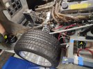
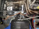
Made a LOT of progess. Need to change fitting #7 to a 6" Female/Female hardline, and fix the kink in lower heater-hose.
I also bought all new SS radiator tubing, as 64" in kit wasn't long enough to reach radiator hoses, so I am making them 67", to get more bit on pipe (yes - bead rolling ends). Then ThermoTech wrap before install.


I also bought all new SS radiator tubing, as 64" in kit wasn't long enough to reach radiator hoses, so I am making them 67", to get more bit on pipe (yes - bead rolling ends). Then ThermoTech wrap before install.