Chuck and Ryan's RCR Build

Thanks Howard and Rob.

Question:

Does any one know where the DIP switches on the back of the speedometer should be set when the sensor is mounted on the front hub with 24" diameter tires, as we have done here? (the "stock" RCR configuration). I would think that the settings would be reasonably uniform from car to car configured in the same manner. For those that have not installed their gauges permanently it sure would be nice to pre set the DIP switches to get a reasonably close speed reading.
 
I love your build thread. What a great build. One suggestion, generally accepted practice in instrumentation wiring is to ground only one end of a shield in a shielded cable. I believe it has to do with ground loop currents causing biasing in the signal wires.
 
I am working on the dip switches right know. I should have it sorted by the weekend. The speedo read about 90 when I was going 60. You could start with that.
 
SRF#42:

Thanks for the info:

One suggestion, generally accepted practice in instrumentation wiring is to ground only one end of a shield in a shielded cable. I believe it has to do with ground loop currents causing biasing in the signal wires.

That is a new one on me. Thanks for the tip. If I get any weird interference, I will clip the shield ground at the power board end, since the shield ground at the sensor end adds some mechanical support to the wiring harness.

Chuck
 
Dean:

Thanks Dean. Once I know your DIP switch settings I may pre - set mine to get, hopefully, in the ball park.

I noticed, just spinning the wheel, that the speedo dropped rather suddenly from about 15 mph to 0 mph as the wheel gradually slowed down. I assume this is related to the number of pulses needed to establish a signal and is normal. Does yours do the same?

I may be getting a bit ahead of myself, since it may not be fair to draw to many conclusions about the speedo's function from spinning a wheel while the car is up on jacks.
 
Well, I'll certainly follow this one. I just installed my sensor on the front wheel in the same position you used, Chuck. I still have to install the connectors on the end of the wiring harnesses, so I can check it yet. Having a good switch baseline would be very helpful.
 
Speedometer Sensor Wire Harness

This post may come under the category of TMI (too much information). There are many tricks to wiring and differing opinions about what is the best technique. For what it is worth, the following is how we made the wire harness for the speed sensor. Keeping in mind it is in an exposed location and will be subjected to a lot of abuse, we thought a bit of extra care was warranted.

Hopefully the pictures will tell the story without further comment, other than to note that a quarter inch diameter length of Painless Powerbraid Wire Wrap, #70901, was used. It was secured at each end with a two inch length of heat shrinkable tubing.

All connections were soldered. The connections were staggered. Each was separately covered with heat shrink tubing and then all three were covered with another piece of heat shrink.
 

Attachments

  • SpeedoWire1.JPG
    SpeedoWire1.JPG
    89.9 KB · Views: 597
  • SpeedoWire2.JPG
    SpeedoWire2.JPG
    83.2 KB · Views: 619
  • SpeedoWire3.JPG
    SpeedoWire3.JPG
    81 KB · Views: 544
  • SpeedoWire4.JPG
    SpeedoWire4.JPG
    83.2 KB · Views: 674
Remote Oil Filter and Recovery Tank

A Canton 5060 remote oil filter adaptor and Canton 5065 remote oil filter mount were used. These are nicely made with a black powder coated finish. The filter mount has extra ports so that a temperature sensor and / or remote oil cooler can be easily added at a later date. Ninety degree adaptors were needed on the oil filter adaptor. It took a bit of manipulation to persuade the oil lines to clear the AC compressor, oil pan and engine mount. It is a tight fit. A two foot length of ¾ inch diameter Painless Powerbraid Wire Wrap was placed over the lower portion of each of the two stainless steel braided hoses to minimize chaffing from adjacent surfaces.

The oil filter adaptor and remote oil filter mount are available from Tri-State Motor Sports: http://www.tristatemotorsports.com/Home.cfm

In keeping with the monochromatic theme, black AN fittings rather than the usual red and blue were used on the oil filter adaptor.

The recovery tank is a Canton 80-201, two quart capacity. It matches the expansion tank. Coolant is carried from the expansion tank to the recovery tank through a rigid aluminum line on top of the sponson along side the engine, then a three eighths inch rubber hose approximately one foot long was routed under the half shaft along side the shifter cables to the base of the recovery tank.

A short length of three eighths inch hose can be seen hanging out the back end of the recovery tank. That over flow hose will be ‘cleaned up’ later, perhaps with a collection tank mounted aft of the oil filter. That detail is rather low on the priority list at the moment and won’t be needed until the GT is driven on a track.

The Audi transaxle has a number of unused threaded holes each of which is just begging for a good screw. A good location for mounting the remote oil filter and the coolant recovery tank was needed. We took advantage of those threaded holes. Two brackets were secured on either side of the transaxle using three bolts each, providing a neat, symmetrical arrangement. The brackets were fabricated from eighth inch aluminum and painted the usual low gloss engine black. The shape of the brackets was dictated by the design of the recovery tank, and the same dimensions were used on the opposite side to support the remote oil filter. Nylon spacers move the brackets one inch out from the transmission to provide clearance. Eventually the aft edge of the brackets will be tied to a bracket to support the exhaust pipes, explaining the unused holes on the brackets.
 

Attachments

  • OilFilterRecovMar08A.JPG
    OilFilterRecovMar08A.JPG
    164.6 KB · Views: 1,090
  • Bracket Pattern 2.JPG
    Bracket Pattern 2.JPG
    93.4 KB · Views: 776
  • RecovTankMar08B.JPG
    RecovTankMar08B.JPG
    163.8 KB · Views: 1,005
  • OilFilterMar08A.JPG
    OilFilterMar08A.JPG
    169.3 KB · Views: 1,046
Chuck, what exactly is the purpose and the function of the recovery tank ?
Does it take the overflow of the expansion tank ?
If so, what does happen with this overlow afterwards ? Will it be sucked back into the cooling circle somehow ?
BTW have i missed the post regarding the expansion tank ? CHecked the whole thread. didn´t find it
Would be interesting to see a drawing of your whole cooling system.

Thanks
TOM
 
Tom

I am putting together a lengthy post addressing your questions. Give me about fifteen minutes to pull it together.

Chuck
 
Radiator Plumbing Revisited

Disclaimer: Ryan and I are neither engineers nor mechanics. We have never worked in a car shop and no one has ever paid us for any mechanical advice. The theories and terminology that follows may be flawed, so take these ideas for what they are worth. But the system described works well. Most of these ideas have appeared in other places, so we make no claim to any original thought.

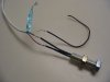
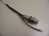
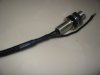
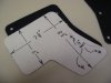
Thermostat: A 185 degree thermostat was used. An eighth inch hole was drilled on one side, and the hole was placed in the 12 o’clock position in the thermostat housing, to permit air to pass through when the system was purged. The housing was fabricated from a standard cast housing as described in an earlier post.

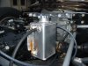
Expansion tank: There is often confusion about what to call the tanks used in the system. The pressurized tank is what I call the expansion tank. It is a Canton tank , #80-200, which has a one and quarter quart capacity. It is small. It is positioned so that the vent hose directly below the cap is at a level that is just slightly above the pipe exiting the thermostat housing. In other words, it is the highest point in the system. That is very important.

The expansion tank has three connections. The large, lower most connection, goes to the lower of the two 5/8” fittings on the water pump. This is how the system is filled with coolant Both of those water pump connections are INPUT. The top fitting is connected to the bypass connection on the thermostat housing. A standard Ford 302 bypass hose, vintage 1980’s, fits perfectly. This bypass connection is important. Don’t ignore it.

The smaller connection near the top of the Canton expansion tank is used for the vent line to the radiator.

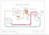
A 3/8” vent line is connected from the expansion tank to the top of the cool side of the radiator (input to the water pump). A previous post discussed this in greater detail. This serves as a purge line. Since there is a small hole in the thermostat, there is some small amount of coolant moving through the radiator back into the expansion tank, and back into the engine even when the thermostat is closed. This accomplishes two purposes: first it keeps the fluid moving and thus constantly purging any air out of the system. Second it helps reduce the temperature variation when the thermostat opens, since some warmed antifreeze is already passing through the system.

A 13 pound STAT radiator cap was used. There does not seem to be any good reason to use a higher pressure cap and doing so may create other problems – like leaks.

So how can air in the top of the radiator flow down a tube, then up into the expansion tank thus purging the system of air? Remember, I am not an engineer or a mechanic. I don’t know. Perhaps it has something with the air expanding when heated and the movement of the fluid. But I do know that this system seems to work just fine.

Recovery tank: Just as there is confusion about what to call the expansion tank, likewise there is confusion about what to call the recovery tank. I am referring to the non pressurized tank that collects the overflow from the expansion tank and then permits it to flow back when the engine cools. This is different than a collection tank, which only catches the overflow but does not siphon it back (to keep coolant off of the race track). We don’t plan to add a collection tank since we have a recovery tank, but if a track requires it, one can be easily added to the output of the recovery tank.

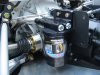
The GT uses quite a bit of antifreeze, what with two long tubes feeding a radiator at the opposite end of the car. So a decent sized recovery tank was selected: a Canton two quart unit, #80-201. It is a nice unit. It matches the expansion tank in that it is made of aluminum and has a nice ‘sixties’ look. It has a tube on the side to see the fluid level. And it comes with a non pressurized cap that looks just like the fuel cap on a 1966 Cessna 172.

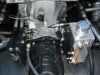
Since the recovery tank is filled from the overflow, which is sucked back into the system as the engine cools, location is not as critical as it is with the expansion tank. We found a nice spot by the transmission about six inches below and three feet aft of the expansion tank.

Once the system is purged and the antifreeze topped off, do not remove the radiator cap from the expansion tank. Instead fill the system at the recovery tank, keeping it about one third full when cold.

First Start: Anytime the integrity of the system is compromised by removing a hose, one needs to purge it. When filling the system initially, the vent on the hot side of the radiator is opened to permit air to escape while the coolant is poured into the expansion tank. The easiest way is to purge the system after filling it as full as possible is to simply top off the expansion tank, fill the recovery tank about one third, and then start the engine with the cap off of the expansion tank. As it warms some bubbles will appear and the level will drop. Once the engine starts to reach operating temperature, top it off and put the pressure cap on. That will likely do it. As the system purges itself, the level in the recovery tank will rise, and when it cools the level in the recovery tank will drop back down again and remain relatively stable. But we go one step further, just as a bit of extra insurance. The front of the car is jacked up so that the front of the engine is slightly higher than the rear. Then the fitting for the fan thermostat (which is actually where a heater hose could be connected), located just behind the thermostat, is loosened to permit any air to escape. This is the high point on the engine. This little ceremony is repeated any time the seal is broken on the cooling system. After a couple of heat cycles the level in the recovery tank will stabilize and the engine temperature remain relatively constant.
 

Attachments

  • DiagramCoolantPlumbing.jpg
    DiagramCoolantPlumbing.jpg
    32.7 KB · Views: 1,083
  • Expansion Recovery Tank.JPG
    Expansion Recovery Tank.JPG
    206.5 KB · Views: 1,165
  • Expansion Tank 2.JPG
    Expansion Tank 2.JPG
    172.1 KB · Views: 1,007
  • RadiatorVent2.JPG
    RadiatorVent2.JPG
    145.6 KB · Views: 815
  • RecovTankMar08B.JPG
    RecovTankMar08B.JPG
    163.8 KB · Views: 827

Randy V

Moderator-Admin
Staff member
Admin
Lifetime Supporter
Chuck - Excellent as usual. With the exception of the 3/8" line running from the radiator to the expansion tank, that is exactly how I've done all the Cobras I've done and it has worked great.

I have somewhat different plans for my Forty as I outline in the Cooling section on my website - but the basic concept is still the same.. I'll post more later on my own build thread if I can ever figure out how to capture photos from my website to be used here..

I just want to also thank you on behalf of many who will get great value from your build log.
While you and Ryan may not be automotive engineers, you've proven that with determination and a logical approach you can accomplish nearly anything.
My Grandfather and Father taught me that as well.. I'm still working on it..
Kudos guys... :thumbsup:
 
This information is so helpful. And you are very thorough in your instructions. One question: Whare did you locate the expansion tank?

Thanks
Bill D
 
Randy:

Thanks for the kind comments. When we started our Cobra project two years ago we were like fish out of water searching for the most basic information about car building which at the time was like Greek to us. We found a nice post chronicalling an ERA build with lots of little details, which proved very reassuring. When we started this project, we thought we would share what little we have learned to help out others in a similar situation. There is lots of info available on Cobras but not so much on GTs.

Bill:

The expansion tank is mounted on the right side of the fire wall. You can identify it by the red lever on the STAT radiator cap in two of the pics posted above. The recovery tank is on the right rear on the tranny.

I should note that even though the expansion tank is small and mounted as low as possible while keeping it at the highest point in the system, we still had to cut out a bit of fiberglass from the clip to clear it. I will cover the mods to the clip in a later post. This, of course, explains why the original GTs had such a convoluted looking expansion tank to provide the clearance and yet keep the top high enough to purge the system.
 
Thanks Chuck. My car is being painted today, so modifying the rear clip is out. I may have a custom (slimline) tank fabricated to fit my available space. Thanks for the explanation and pictures as they are very useful.

Cheers
Bill D
 

Pat Buckley

GT40s Supporter
Nice build thread, Chuck....thanks.

Are you sure that BOTH water pump connections are INPUT?


"The expansion tank has three connections. The large, lower most connection, goes to the lower of the two 5/8” fittings on the water pump. This is how the system is filled with coolant. Both of those water pump connections are INPUT. The top fitting is connected to the bypass connection on the thermostat housing. A standard Ford 302 bypass hose, vintage 1980’s, fits perfectly. This bypass connection is important. Don’t ignore it."
 
As Randy always says, "when it comes to wp fittings they both suck." In a stock configuration, one is input from the thermostat bypass and the other is input from the heater core.

Great post Chuck, thanks. I took my air bleed input from the rear of the manifold. Other than that, I used the same approach.
 
Back
Top